User’s Manual MKP 2000 Remote Control Panel www.extron.com Extron Electronics, USA Extron Electronics, Europe Extron Electronics, Asia Extron Electronics, Japan 1230 South Lewis Street Anaheim, CA 92805 USA 714.491.1500 Fax 714.491.1517 Beeldschermweg 6C 3821 AH Amersfoort The Netherlands +31.33.453.4040 Fax +31.33.453.4050 135 Joo Seng Road, #04-01 PM Industrial Building Singapore 368363 +65.6383.4400 Fax +65.6383.4664 Kyodo Building 16 Ichibancho Chiyoda-ku, Tokyo 102-0082 Japan +81.3.3511.
Precautions Safety Instructions • English This symbol is intended to alert the user of important operating and maintenance (servicing) instructions in the literature provided with the equipment. This symbol is intended to alert the user of the presence of uninsulated dangerous voltage within the product's enclosure that may present a risk of electric shock. Caution Read Instructions • Read and understand all safety and operating instructions before using the equipment.
Quick Start Guide — MKP 2000 Install and set up the MKP 2000 as follows: Step 1 Turn all of the equipment off and disconnect it from the power source. Step 2 Install the cables to and from the control panel in a wall, podium, or desk. See Rear Panel and Side Panel Connections in chapter 2, Installation, for guidelines. Step 3 Prepare the wall, podium, desk, or other surface to mount the MKP. See Preparing the site, installing the mud ring or wall box in chapter 2, Installation.
Quick Start Guide — MKP 2000, cont’d Step 10 Program the control panel with the size of the connected switcher. See System Settings Page in chapter 5, HTML Operation. Step 11 Use the control panel to select inputs and outputs. See Front Panel Operations in chapter 3, Local Operation. Table of Contents Chapter 1 • Introduction .......................................................... 1-1 About the MKP 2000 Remote Control Panel ........... 1-2 RS-232 connection to the switcher .............................
Table of Contents, cont’d Symbol definitions for MKP SIS commands ......................... 4-6 Command/response table for MKP SIS commands .............. 4-8 MKP 2000 Remote Control Panel Chapter 5 • HTML Operation .................................................. 5-1 Dowload the Startup Page ............................................... 5-2 System Status Page .............................................................. 5-4 System Settings Page .......................................................
Introduction This manual provides installation and operation instructions for the Extron MKP 2000. Input 13 C About the MKP 2000 Remote Control Panel The MKP 2000 is a network-ready remote control panel that can control any Extron matrix switcher. The MKP’s RS-232 ports allow it to communicate with other devices (another MKP or a matrix switcher) locally and its Ethernet port allows it to communicate with multiple devices.
Introduction 2 Chapter Two Installation MKP Installation Overview UL Requirements for Wall Box Installation Installation Procedures Rear Panel and Side Panel Connections 1-4 MKP 2000 Remote Control Panel • Introduction MKP 2000 Remote Control Panel • Introduction
Installation CAUTION Installation and service must be performed by authorized personnel only. UL Listed electrical boxes are recommended. See UL Requirements for Wall Box Installation on the next page. UL Requirements for Wall Box Installation The following Underwriters Laboratories (UL) requirements pertain to the installation of the MKP 2000 into a wall or furniture (figure 2-1). The MKP 2000 remote control panel should be installed in a standard, 2-gang electrical wall box (figure 2-1).
Installation, cont’d Preparing the site, installing the mud ring or wall box Choose a location that allows cable runs without interference. Allow enough depth for both the wall box and the cables. You may need to install the cables into the wall, furniture, or conduits before installing the control panel. 5. If you are using a wall box, feed cables through the wall box punch-out holes, and secure them with cable clamps to provide strain relief. 6.
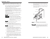
Installation, cont’d 7a. If you are using a mud ring, follow the directions, if any, that came with the mud ring to attach the clips that fasten the ring to the wall or furniture (figure 2-3). Wall Stud To meet the UL listing requirements, this device must be installed in a wall box. Wall Box Sheet Rock Backing Clip 0.75" #6-32 Screw Mounting Bracket Detail A Sheet Rock Screws or Nails Backing Clip Flush with Wall Surface Figure 2-4 — Attaching a wall box to a wall stud 1.
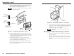
Installation, cont’d 3. Mount the MKP’s faceplate to the mud ring or wall box with machine screws (figure 2-5). 1 LAN (Ethernet) port — If desired, connect a Category (CAT) 5e or higher (network) cable between this connector and either the matrix switcher to be controlled or to an Ethernet local area network (LAN). LAN See TP cable termination, on page 2-12, to properly wire the RJ-45 connector for your application.
Installation, cont’d Control connections The MKP has two RS-232 ports; a Host port ( port ( 2 ); and an Ethernet (LAN) port ( 3 ). ) and a Switcher 1 Any number of control panels can be connected, as part of a network, to any Ethernet-enabled matrix switcher via the switcher’s Ethernet port (figure 2-10). All TP cables in this example are wired as patch (straight) cables. An MKP control panel can be directly connected to any Extron matrix switcher through the switcher’s RS-232 port (figure 2-8).
Installation, cont’d TP cable termination It is vital that your Ethernet cables be the correct cables, and that they be properly terminated with the correct pinout. Ethernet links use Category (CAT) 5e or CAT 6, unshielded twisted pair (UTP) or shielded twisted pair (STP) cables, terminated with RJ-45 connectors. Ethernet cables are limited to a length 328' (100 m). Patch (straight) cable Pin Side Clip Down 12345678 Pins RJ-45 connector Do not use standard telephone cables.
Installation, cont’d Power supply wiring MKP 2000 Remote Control Panel Figure 2-12 shows how to wire the connector. Smooth Ridges A 12 V GND A 0.2” (5 mm) SECTION A–A Power Supply Output Cord Direct Insertion Connector Figure 2-12 — Power connector wiring CAUTION Power supply voltage polarity is critical. Incorrect voltage polarity can damage the power supply and the MKP. Identify the power cord negative lead by the ridges on the side of the cord (figure 2-12).
Local Operation The LED display shows the most recent input or output number entered on the numeric keys only. Ties created using other devices (other MKPs, a PC or control system, or the matrix switcher’s front panel) are not shown in the LED display. Front Panel Controls and Indications 1 2 3 4 5 6 7 8 9 BACK 0 CANCEL Front Panel Operations 7 1 INPUT OUTPUT Creating a tie 1. TAKE Press the Input button to specify that the next number entered is an input number. • The Input LED lights.
Local Operation, cont’d When an input or output outside the available range for this MKP or the connected matrix switcher is selected, the LED display shows N-A. Viewing the last input or output tied from the MKP Press either the Input button or the Output button. • The Input or Output LED lights. • The LED display shows the last tied input or output (depending on which LED, Input or Output, is lit). The LED display shows the most recent input or output number entered on the numeric keys only.
Local Operation, cont’d Simultaneously press and hold the buttons for 2 seconds. Release the buttons. INPUT OUTPUT The LED display shows the most-significant octet of the MKP 2000’s IP address. Press the Output button to cycle through the displayed and editable octets. TAKE OUTPUT INPUT MKP 2000’s IP Address OUTPUT OUTPUT OUTPUT Press the Input button to cycle through the displayed and editable addresses and to reach the MKP set-up settings.
Local Operation, cont’d Control panel security lockout (executive mode) The front panel security lockout limits the MKP’s front panel operation to input and output selection only (IP address modification is locked). Perform a soft reset of the MKP as follows: 1. To toggle the lock on and off, press and hold the 1, 3, Back, and Cancel buttons for approximately 3 seconds until the LED display shows the appropriate “LOC” (on or off) message (figure 3-3).
Local Operation, cont’d Performing a hard reset The hard reset function restores the MKP to the original factory default settings, including the default (factory) firmware configuration and the default IP settings. A hard reset performs all of the reset-whole-MKP functions, absolute reset functions, and erases all user-installed software or firmware.
SIS Operation RS-232 Links Ethernet Link The MKP’s rear panel 3-pole, 3.5 mm, Host RS-232 connector (figure 4-1) can be connected to the RS-232 serial port output of a host device such as a computer running the HyperTerminal utility, an RS-232 capable PDA, or a control system. This connection makes software control of the control panel possible. The rear panel Switcher connector can be connected to the Remote or RS-232 port of a matrix switcher.
SIS Operation, cont’d This message means that the switcher requires an administrator or user level password before it will perform the commands entered via this link. The switcher repeats the password message response for every entry other than a valid password until a valid password is entered. ASCII to HEX Conversion Table Space Login Administrator Login User The switcher initiates the login message when a correct administrator or user password has been entered.
SIS Operation, cont’d Symbol definitions for MKP SIS commands X11 = Name = CR/LF (carriage return/line feed) (0x0D 0A) • = space X1 = On/off status 0 = off/disable 1 = on/enable X2 = RS-232 port number 1 = host 2 = switcher X3 = n=–1= redirect serial port data from the specified port to allow for a transparent pass through mode. The response is returned with leading zeroes. n = the maximum number of serial ports that the IP link supports. X5 is verified at this port.
4-8 (MKP to host) 1x 0x x Esc X2 CD Esc X2 *0CD Esc 1*2*50*10D*CD Esc X2 * X3 * X4 * X5 CD MKP 2000 Remote Control Panel • SIS Operation MKP•2000 60-682-00 Report model name. See Appendix A for part numbers. X6 Firmware version x.xx. X7 Provide a detailed status of the Ethernet protocol firmware, the MKP controller firmware, and any firmware upgrade. The firmware that is running is marked by asterisk (*). A caret (^) indicates that the firmware has a bad checksum or an invalid load. ?.
4-10 X19 SI Ips X17 X17 Ipg X17 X17 Esc X17 CS Esc CS Esc X17 CG Esc CG Set subnet mask Read subnet mask MKP 2000 Remote Control Panel • SIS Operation Ipa X20 Ipa• Esc X20 CA Set administrator password Clear administrator password X17 or the X19 variable, but not both. The response is as shown Set the switcher to display the local time as Daylight Savings Time (+1 hour) in summer months.
SIS Operation, cont’d MKP 2000 Remote Control Panel 5 Chapter Five HTML Operation Download the Startup Page System Status Page System Settings Page Port (RS-232) Settings Page Passwords Page Firmware Upgrade Page File Management Page Special Characters 4-14 MKP 2000 Remote Control Panel • SIS Operation
HTML Operation The MKP can be configured through its Ethernet port, connected via a LAN or WAN, using a web browser such as Microsoft’s Internet Explorer. The browser’s display of the MKP’s configuration has the appearance of web pages. This chapter describes the factory-installed HTML pages, which are always available and cannot be erased or overwritten. 5. Press the keyboard Enter key. The MKP checks to see if it is password protected. If the MKP is not password protected, proceed to step 7.
HTML Operation, cont’d System Status Page System Settings Page The System Status page (figure 5-2) provides an overall view of the status of the MKP, including various IP addresses, the status of the Host and Switch RS-232 ports, and the voltage. The System Status page is the default page that the switcher downloads when you connect to the MKP. Access the System Status page from other MKP HTML web pages by clicking the Status tab.
HTML Operation, cont’d IP Settings section Unit Name field The Unit Name field contains the locally-assigned name of the MKP. This name field can be changed to any valid name, up to 24 alphanumeric characters. The following characters are invalid in the unit name: + ~ , @ = ‘ [ ] { } < > ’ “ ; : | \ and ?.
HTML Operation, cont’d Authorized inputs and authorized outputs Port (RS-232) Settings Page You can use the Authorized Inputs and Authorized Outputs drop boxes to narrow the number of inputs and outputs that are controllable from the MKP. The Port Settings page (figure 5-4) allows you to configure the MKP’s two (Host and Switch) RS-232 ports. Access the Port Settings page by clicking the Configuration tab and then the Port Settings link on the left side of the System Settings page.
HTML Operation, cont’d Passwords Page Firmware Upgrade Page Access the Passwords page (figure 5-5) by clicking the Configuration tab and then the Passwords link on the left side of the System Settings page. System (IP) Settings Port Settings Firmware Upgrade System (IP) Settings Port Settings Passwords Figure 5-5 — Passwords page The fields on the Passwords page are for entering and verifying administrator and user passwords.
HTML Operation, cont’d 7. Click the Browse button. An open file window appears (figure 5-7). File Management Page To delete files such as HTML pages from the switcher or to upload your own files to the switcher, click the File Management tab. The switcher downloads the file management HTML page (figure 5-8). Figure 5-7 — Firmware upgrade open file window 8. Navigate to the folder where you saved the firmware upgrade file. Select the file. Valid firmware files must have the file extension ‘.S19’.
HTML Operation, cont’d Special Characters The HTML language reserves certain characters for specific functions. The MKP will not accept these characters as part of its name, passwords, or locally created file names.
Reference Data Specifications Part Numbers MKP 2000 Remote Control Panel Control/remote — keypad Extron remote key pad control .. (2) 3.5 mm, 3-pole captive screw connectors General External power supply ............... 100 VAC to 240 VAC, 50/60 Hz, external, autoswitchable; to 12 VDC, 1 A, regulated Power input requirements ......... 12 VDC, 350 mA Temperature/humidity ..............
Reference Data, cont’d Mounting and Cabling Specifications Electrical box cutout Any standard box that meets the local electrical codes can be used, but boxes from different manufacturers can have different size openings. Extron recommends testing the fit of the MKP inside the electrical box and then placing the box flush against the mounting surface and tracing the cutout area. 3.
Reference Data, cont’d Extron Comm-Link cable Wire specifications for Extron Comm-Link cable (figure A-2) are as follows: A (red) = 18 AWG B (violet or blue) = 22 AWG (grouped and shielded) C (white) = 22 AWG D (Drain) = 24 AWG E (black) = 18 AWG Comm-Link cable was designed for use with MKP control panels g Figure A-2 — Comm-Link cable A-6 MKP 2000 Remote Control Panel • Reference Data