MPS 112 and MPS 112CS Media Presentation Switchers 68-706-01 Rev.
Precautions Safety Instructions • English This symbol is intended to alert the user of important operating and maintenance (servicing) instructions in the literature provided with the equipment. This symbol is intended to alert the user of the presence of uninsulated dangerous voltage within the product's enclosure that may present a risk of electric shock. Warning Power sources • This equipment should be operated only from the power source indicated on the product.
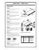
Quick Start — MPS Series Installation Step 1 Turn off power to the MPS switcher and all other devices that will be connected. Mounting Screws (2 Plcs) Each Side Optional Furniture Mounting Bracket Step 2 MP (VI DE O) OU S 11 OG T PR OU 2 T 4 3 Select your mounting option and install the appropriate brackets. Mount the switcher.
Quick Start — MPS Series, cont’d Optimizing the audio 1. Finish installation and wiring as described on the previous page, turn on all equipment, and provide an input signal to the MPS switcher. 2. Reset program audio volume by pressing and holding the Mode button, then pressing and releasing the Prog Vol Reset button. Release the Mode button to return to normal operating mode. 3.
Table of Contents Chapter 1 • Introduction ................................................................................. 1-1 About the MPS Series ......................................................................................... 1-2 MPS Series Features ............................................................................................ 1-2 Chapter 2 • Installation ..........................................................................................................
Table of Contents, cont’d Chapter 4 • Windows®-based Control Program ..................................................... 4-1 Installing the Windows-based Control Software ............................................... 4-2 Using the Software ............................................................................................................ 4-2 Uploading Firmware Updates ....................................................................................... 4-3 Chapter 5 • Programmer’s Guide ....
MPS Series 1 Chapter One Introduction About the MPS Series MPS Series Features
Introduction About the MPS Series The Extron MPS 112 and MPS 112CS are media presentation switchers featuring three A/V switchers and a program audio switcher with microphone pre-amplifier and mute controls in one product. The A/V switchers include a four input, one output VGA/audio switcher, a four input, one output S-video/audio switcher, and a four input, one output composite video/audio switcher.
MPS 112 Series 2 Chapter Two Installation Mounting the Switcher Rear Panel Connectors Connecting the MPS Switcher
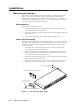
Installation Mounting the Switcher The MPS 112 and MPS 112CS are housed in 1U high, 17.4" wide metal enclosures that are rack- or desk-mountable. The appropriate rack/desk mounting kit (#70-077-03) is included with the switchers. The switchers may also be surfacemounted under a table, desk, or podium, or on a wall, using an optional Extron 1U enclosure under-desk mounting kit (#70-222-01). Rack mounting Rack mount the switcher as follows: 1.
5. Align the mounting screws with the slots in the brackets and place the switcher against the surface, with the screws through the bracket slots. 6. Slide the switcher slightly forward or back, then tighten all four screws to secure the switcher in place. Through-desk mounting Mount the switcher through a desk or podium as follows: 1. Attach the supplied mounting brackets to the switcher with the machine screws provided (figure 2-1). 2. Cut the proper sized hole in the mounting surface. 3.
Installation, cont’d 5 S-video output — One female 4-pin mini DIN for S-video output. 6 VGA input group — Four female 15-pin HD connectors for VGA input (numbered 1 to 4). 7 VGA output — One female 15-pin HD connector for VGA output. 8 RS-232 remote — One female 9-pin D connector for a host computer or third party controller using Extron’s Simple Instruction Set (SIS) or control software for Windows. 9 (VGA) audio input group — Four 3.5 mm, female, stereo mini jacks for audio input.
3 Attach up to four VGA, four S-video, and four video (composite) input devices to the MPS switcher. 4 Connect the switcher’s VGA, S-video and video (composite) outputs (up to three, one of each video format) to a projector’s inputs. 5 For stereo audio input, connect up to 12 audio sources to the switcher’s audio inputs of the VGA, S-video, or video (composite) groups (up to 4 for each group). See the following Audio input and output section for connections.
Installation, cont’d Audio input and output Connecting the RCA audio connectors 1. Use pre-made RCA audio cables, or cut bulk audio cable, terminate the RCA plugs on the cable as shown in figure 2-5. 2. Plug RCA connectors into the MPS switcher. Tip (Signal) Right Channel (Red Jacket) Sleeve (Gnd ) Left Channel (White Jacket) Tip (+) Sleeve ( ) Figure 2-5 — RCA audio connector Connecting the 3.5 mm mini-plugs 1. Use pre-made Extron 3.5 mm audio cables, or cut bulk audio cable, solder the 3.
Connecting the 3-pole captive screw microphone connector (MPS 112CS) 1. Use a pre-made 3-pole captive screw microphone cable, or cut bulk microphone cable, and attach the 3-pole captive screw connector to the cable. 2. Plug the 3-pole captive screw connector into the MPS 112CS. Tip Ring Sleeve Tip Sleeve Unbalanced Mic Input Balanced Mic Input Figure 2-8— 3.
Installation, cont’d Remote connection The cable used to connect the RS-232/Remote port to a computer or control system may need to be modified by removing pins or cutting wires. If unneeded pins are connected, the switcher may hang up. For RS-232 control, use a control cable with only pins 2, 3, and 5 connected. Otherwise, either cut the wires to the other pins in hard-shelled connectors or remove the unneeded pins from molded plugs.
MPS 112 Series 3 Chapter Three Operation Front Panel Features Front Panel Operation
Operation Front Panel Features 1 2 3 4 MPS SERIES EXEC.MODE MEDIA PRESENTATION SWITCHER VGA / AUDIO 4 1 S-VIDEO / AUDIO 2 3 4 1 VIDEO / AUDIO 2 3 PROGRAM AUDIO 1 2 3 MODE SINGLE SEPARATE PROG VOL RESET MIC VOL RESET MIC POWER ON/OFF MUTE 14 13 12 11 10 9 8 MIC 4 VOLUME VOLUME MIX 7 6 5 Figure 3-1 — Front panel details of the MPS switcher (MPS 112 shown) 1 Executive Mode indicator LED — This red LED lights when Executive mode is turned on.
Switcher Mode controls 12 Separate Switcher mode — This is the secondary function of this button. Press and release this button while pressing and holding the Mode button ( 14 ) to select the Separate Switcher mode. The associated LED indicates if the Separate Switcher mode is on (when lit) or off. When the Mode button is released, the LED resumes input indication. 13 Single Switcher mode — This is the secondary function of this button.
Operation, cont’d View mode To view the switcher’s current mode and microphone power settings, press and hold the Mode button for more than 2 seconds. The LEDs on the front panel change from input indication to setting indication. To change a setting, continue to hold the Mode button and press the button that corresponds to the setting you want to change. Figure 3-3 shows the front panel buttons and LEDs that are active during View mode.
Front panel security lockout (Executive mode) To prevent unauthorized changes, when Executive mode is on it locks all functions except input selection functions and Program Audio Volume control. To toggle the Executive mode on or off, press and hold the Mode button for more than 2 seconds until the front panel LEDs change to View mode, then press and release the fourth input button of the VGA/Audio group. The Exec Mode LED turns on to indicate that executive mode is on, off to indicate off.
Operation, cont’d Program audio mute To mute the program audio output, press the Program Audio Mute button. The indicator LED to the right of the button will light when the program audio is muted. Press the Program Audio Mute button again to unmute the output. Program audio mute does not mute the microphone.
MPS Series 4 Chapter Four Windows®-based Control Program Installing Windows-based Control Software Using the Software Uploading Firmware Updates
Windows©-based Control Program The Windows-based Control Program (Extron part number 29-060-01) for controlling the MPS Series switchers via RS-232 requires Windows 95/98, NT, or later. It provides remote control of MPS switcher functions. Installing the Windows®-based Control Software The program is contained on two 3.5-inch diskettes. The program occupies approximately 2.5 MB (megabytes) of hard-drive space. Run the program from the hard drive.
For information about program features, you can access the help program in any of the following ways: • From the Extron Electronics group folder, double-click on the MPS Help icon. • From within the MPS Control Program, click on the Help menu on the main screen. • From within the MPS Control Program, press the F1 key for contextsensitive help. Uploading Firmware Updates The following procedure is for the MPS Control Program version 1.2 and higher only. If you have version 1.0 or 1.
Windows©-based Control Program, cont’d 8. After opening the file, click OK, then remove power from the unit. Power the unit back up to start uploading the firmware update. The upload process may take several minutes. To ensure that the correct update file is listed, read the text in the window that appears. If the desired file is not listed, click Cancel to return to the Firmware Loader window.
MPS Series 5 Chapter Five Programmer’s Guide Remote Control Port (RS-232) Host-to-MPS Communications Command/Response Table
Programmer’s Guide Remote Control Port (RS-232) The MPS switcher RS-232 port connector is used to connect to a host or external controlling device, such as a computer or control system, which can generate the proper command codes and recognize the switcher’s responses. The cable used to connect the RS-232 port to a computer or control system may need to be modified by removing pins or cutting wires. If unneeded pins are connected, the switcher may hang up.
MPS switcher error responses When the MPS switcher receives an SIS command and determines that it is valid, it performs the command and sends a response to the host device. If the switcher is unable to perform the command because the command is invalid or contains invalid parameters, it returns an error response to the host.
Programmer’s Guide, cont’d Command/response table for SIS commands Command ASCII Command Response (host to switcher) Additional description (switcher to host) Input selection (in Separate Switcher mode only) Video and audio X1 * X2 ! Chn X1 * X2 Group X1 and input X2 are selected. Chn X11 Input Input selection (in Single Switcher mode only) Video and audio ! X11 X11 is selected.
Command ASCII Command Response (host to switcher) Description (switcher to host) System reset (to factory defaults) Reset to factory default Esc ZXXX Zpx Resets system to the following factory defaults: Mode - X7 = 1 Input - X7 = 1 = 70 Main Volume Mic Volume - X4 = 0 Executive Mode - X3 = 0 Mic threshold - X8 = 8 Request information I/i Mod X7 1G X2 2G X2 3G X2 4G= X1 G X2 Displays which input in each group is selected and which input is routed to program audio output.
Programmer’s Guide, cont’d Uploading firmware to the MPS via an SIS command There are two ways to upload firmware to the switcher: • Use the MPS Control Program • Use SIS commands entered via a communication utility such as HyperTerminal. Extron recommends that you use the MPS control Program to upload firmware (See Uploading Firmware Updates on page 4-3) and reserve this SIS procedure for correcting firmware that has been corrupted and is unable to respond to the MPS Control Program.
3. Cycle power to the switcher: disconnect power for a few moments, reconnect power, and press the computer keyboard’s ? (question mark) key. You have approximately 2 seconds or less to press the ? key. If that time lapses and the ? key has not been pressed, repeat step 3. 4. Press D on the keyboard, then type Download. This text is case-sensitive. The computer responds with a “Ready” prompt. 5. Click Transfer > Send text file... . 6. Select All files (*.*) from the Files of type: drop-down box. 7.
PRELIMINARY Programmer’s Guide, cont’d 5-8 MPS Series • Programmer’s Guide
MPS Series A Appendix A Reference Information Specifications Part Numbers
Reference Information Specifications Video Gain ............................................... Unity Bandwidth VGA signals ...................... 350 MHz (-3 dB) S-video signals ................. 250 MHz (-3 dB) Composite video signals .. 300 MHz (-3 dB) Differential phase error .............. 1.0º at 3.58 MHz and 4.43 MHz Differential gain error ................. 1.0% at 3.58 MHz and 4.43 MHz Crosstalk VGA signal group ........... -50 dB @ 10MHz, -30 dB @ 100MHz Switching speed VGA group’s sync ..........
Nominal level VGA outputs .................... 0.7 Vp-p S-video outputs ................ Y: 1 Vp-p (including sync), C: 0.3 Vp-p Composite video outputs 1.0 Vp-p (including sync) Minimum/maximum levels VGA outputs .................... Analog, 0.3 V to 1.5 Vp-p S-video outputs ................ Analog, Y: 0.4 V to 2.0 Vp-p Composite video outputs Analog, 0.4 V to 2.0 Vp-p Impedance .................................... 75 ohms Return loss (VGA output) .......... <-40 dB @ 5 MHz DC offset (max.
Reference Information, cont’d Audio output — individual audio groups (VGA, S-video, composite video) Number/signal type ................... Connectors VGA group ....................... S-video and video groups Impedance .................................... Gain error ...................................... Nominal level ............................... Maximum level (Hi-Z) ................ 1 stereo, unbalanced, per each group (1) 3.
Connectors MPS 112 ............................. MPS 112CS ........................ Impedance MPS 112 ............................. MPS 112CS ........................ Nominal level ............................... Minimum level ............................. Maximum level ............................ (1) 1/4" (6.3 mm) audio connector; tip (signal), sleeve (ground) (1) 3.5 mm, 3-pole captive screw connector >2.3k ohms unbalanced >2.
Reference Information, cont’d Part Numbers Included parts These items are included in each order for an MPS 112: Included parts Replacement part number MPS 112 60-532-01 MPS 112CS 60-532-02 Rack/desk mounting brackets 70-077-03 Tweeker (small screwdriver) 100-014-01 3.5 mm, 3-pole captive screw connector (MPS 112CS only) 10-265-03 3.
Mini High Resolution Cable Part number BNC-4 Mini HR bulk, 500'/1000' 22-032-02/-03 BNC-5 Mini HR bulk, 500'/1000' 22-020-02/-03 Plenum BNC-5 Mini HR bulk, 500'/1000' 22-103-02/-03 Assorted connectors BNC connectors Part number BNC Mini HR crimp connectors, qty. 50 100-074-51 SHR male crimp connectors, qty. 50 100-075-51 BNC bulkhead connectors, qty.
Reference Information, cont’d A-8 MPS Series • Reference Information
FCC Class A Notice Note: This equipment has been tested and found to comply with the limits for a Class A digital device, pursuant to part 15 of the FCC Rules. These limits are designed to provide reasonable protection against harmful interference when the equipment is operated in a commercial environment. This equipment generates, uses and can radiate radio frequency energy and, if not installed and used in accordance with the instruction manual, may cause harmful interference to radio communications.
www.extron.com Extron Electronics, USA Extron Electronics, Europe Extron Electronics, Asia Extron Electronics, Japan 1230 South Lewis Street Anaheim, CA 92805 USA 714.491.1500 Fax 714.491.1517 Beeldschermweg 6C 3821 AH Amersfoort The Netherlands +31.33.453.4040 Fax +31.33.453.4050 135 Joo Seng Road, #04-01 PM Industrial Building Singapore 368363 +65.6383.4400 Fax +65.6383.4664 Daisan DMJ Building 6F 3-9-1 Kudan Minami Chiyoda-ku, Tokyo 102-0074 Japan +81.3.3511.7655 Fax +81.3.3511.