
User Guide

VersaTools™ MSW 4V SDI Mini Switcher • Connections 5VersaTools™ MSW 4V SDI Mini Switcher • Connections
Installation
4
4. For furniture mounting, drill 3/32” (2 mm) diameter pilot holes,
1/4” (6.3 mm) deep in the mounting surface at the marked screw
locations.
5. For furniture mounting, insert #8 wood screws into the four pilot
holes. Tighten each screw into the mounting surface until just less
than 1/4” of the screw protrudes.
6. For furniture mounting, align the mounting screws with the slots
in the brackets and place the MSW against the surface, with the
screws through the bracket slots.
7. For furniture mounting, slide the switcher slightly forward or
back, then tighten all four screws to secure the MSW in place.
Ceiling
Digital Projector
Projector
Mounting
Bracket
M
D
A
4
V
S
D
I
POWER
1
5
V
.
5
A
M
A
X
1
2
3
4
S
D
I
I
N
P
U
T
S
D
I
O
U
T
P
U
T
S
Mounting
Bolt
Projector Mounting Under Desk Mounting
A
/
V
S
W
I
T
C
H
E
R
M
O
D
E
N
O
R
M
A
L
A
U
T
O
A
U
T
O
S
W
I
T
C
H
1
2
3
4
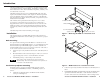
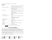
Figure 3 — Desk and projector mounting the MSW
8. For projector mounting, secure the MSW to a projector mount by
inserting the mounting bolt through the bracket’s slotted hole.
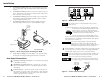
Rear Panel Connections
1
SDI Inputs (1 through 4) connectors — Connect SDI video inputs
to these BNC connectors.
2
SDI Outputs (A and B) connectors — Connect one or two SDI
devices to these BNC connectors. The MSW outputs re-clocked
SDI outputs.
3
Contact connector — Connect a remote contact closure device to
the switcher for remote control of the switcher, or daisy chain the
switcher to other MSWs for remote control of the other switchers,
via this 5-pin captive screw connector
MSW 4V SDI
POWER
12V
.5A MAX
S
D
I
I
N
P
U
T
S
1
2
3
4
CONTACT
1
2
3
4
A
B
S
D
I
O
U
T
P
U
T
S
24 3
1
Figure 4 — MSW 4V SDI rear panel
The switcher must be in normal (manual) mode for contact
closure to work.
To select an input using a contact closure device, momentarily
short the pin for the desired input number to logic
ground (pin 5). To force one of the inputs to be
always selected, leave the short in place. The short
overrides any front panel input selections.
You can also daisy chain multiple MSWs via the
Contact connector for front panel control of all switchers; touch
the input button on one MSW to switch all MSWs. Wire pin 1 to
pin 1, pin 2 to pin 2, and so on.
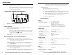
CAUTION
Power supply voltage polarity is extremely important.
Applying power with incorrect voltage polarity could
damage the power supply and the MSW. Identify the power
cord negative lead by the ridges on the side of the cord.
4
Power connector — Plug the external 12V power supply into this
2-pole captive screw connector. The power supply is included
with the unit. Figure 5 shows how to wire the connector.
Do not tin the stripped power supply leads before installing the
captive screw connector. Tinned wires are not as secure in the
captive screw connectors and could be pulled out.
The two power cord wires must be kept separate while the
power supply is plugged in. Remove power before wiring.
Return
+12V
End Captive Screw
Connector
view of
power supply
output cord.
Figure 5 — Power connector wiring
CONTACT
1
2
3
4