MSX1616 / MSX1616HR MATRIX SWITCHER 16–INPUT, 16–OUTPUT MSX1616/MSX1616HR OPERATION MANUAL High Resolution Video Products • A/V System Integration Tools • Interactive Training Systems
Installation and Safety Instructions For Models without a Power Switch: The socket outlet shall be installed near the equipment and shall be accessible. For all Models: No serviceable parts inside the unit. Refer service to a qualified technician. For Models with Internal or External Fuses: For continued protection against fire hazard, replace only with same type and rating of fuse.
Table of Contents MSX1616 Matrix Switcher - Quick Start..................................................................................... 3 Installation ..........................................................................................................................3 Front Panel Controls ...........................................................................................................4 Functionality ........................................................................................
2 Serial Commands ......................................................................................................................... 26 Addressing Commands .....................................................................................................26 Set-Up Commands ............................................................................................................27 Level Commands ......................................................................................................
3 MSX1616 Matrix Switcher - Quick Start Installation Step 7 Step 1 If you will be controlling the switcher with serial commands, cable the control system or computer serial port to serial port 1 based on the type of connection described below. Install the switcher into a standard 19" equipment rack, or set it on a flat surface. Connect input video sources to the BNC connector inputs. Connect sync inputs to the H/C and V connectors and video inputs to the RGB connectors.
MSX1616 Matrix Switcher - Quick Start, continued Front Panel Controls Functionality Buttons to the left of the LCD let you navigate through the LCD menu options. Creating new patches Arrowed buttons let you increase or decrease a selection, scroll up or down, move forward and backward, and change inputs and outputs. MENU displays the status menu on the initial press. Subsequent presses display the next menu level up. ENTER saves newly selected menu settings.
5 Product Overview Description The MSX1616 matrix switcher routes audio and video signals from multiple sources to multiple monitors, screens, and speakers without requiring cable changes.
6 • Dual Switching Modes o Matrix mode – Lets you configure new or change existing input-output patches with the press of one button. o Express mode – Lets you recall previously stored input/output patches. • RGB Delay mode for enhanced switching translations. • 256 Configuration Memories let you to store and recall input/output configurations, audio levels, and auxiliary serial commands. • Blank Front Panel Versions are available at a lower cost.
7 Installation Mounting the MSX1616 Mount the MSX1616 switcher on a standard 19-inch metal equipment rack. The unit is 6U tall. Allow 1U above and below the switcher for heat dissipation. To rack-mount the switcher: 1. Slide the switcher into the equipment rack. 2. Align the mounting holes of the unit with those of the rack. 3. Fasten the switcher to the rack using the machine screws included with the rack.
8 Video Input and Output Connections Video connections are made with BNC connectors, one for each of five inputs: Red (R), Green (G), Blue (B), Horizontal/Comp Sync (H/C), and Vertical Sync (V). 1. Connect video input devices to the appropriate video input connectors. 2. Connect video output devices to the appropriate video output connectors.
9 Serial Ports The switcher features three serial ports that can accommodate RS-232, RS-422, and RS-485 connections. Use serial port 1 to control the switcher using either a PC or a third-party control system. Use serial ports 2 and 3 to control auxiliary devices with serial commands you store into the switcher.
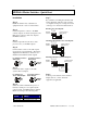
DIP Switch Settings: Termination Switch 1 Position 2 Switch 1 Position 3 Switch 1 Position 4 Switch 1 Position 5 Switch 1 Position 6 Switch 2 Position 1 Switch 2 Position 2 RS232 OFF OFF OFF OFF OFF OFF OFF OFF OFF Do not terminate 422/485 Full duplex termination ON ON ON ON ON ON ON ON ON Terminate if first or last position OFF Do not terminate if center of multi-drop connection OFF Only one termination required at ends OFF Do not terminate if center of multi-drop 485 ha
11 MSX1616 DIP switch ON position: MSX3216 DIP switch ON position: 2002 - INLINE, INC. MSX1616 OPERATION MANUAL - v1.
12 Compatibility Input The MSX1616 16 input connections are terminated with BNC connectors that can accept composite, S-Video component (YUV, YPrPb, YR-Y, B-Y), RGBHV, RGBS, RGsB, or computer pass through singles. You can configure a single input to feed up to 16 different output sources simultaneously, giving you 32 possible input/output configurations. The MSX1616 has analog audio-follow-video and breakaway capability.
13 2002 - INLINE, INC. MSX1616 OPERATION MANUAL - v1.
14 MSX1616 OPERATION MANUAL - v1.0 5/8/02 2002 - INLINE, INC.
15 Operation Front Panel Controls The MSX1616 features the following ergonomic front panel controls. Button Function Soft Keys Menu Navigation Buttons MENU ENTER VOLUME TAKE Navigate through any menu on LCD. Scrolls up and down LCD menu selections and changes inputs/outputs. CANCEL BLANK PRESET INPUT OUTPUT 2002 - INLINE, INC. Displays the previous LCD screen. Saves changes made to existing patches and saves any new settings. Adjusts volume of selected audio output or input.
16 Front Panel Operation The MSX1616 series has three operational modes: Matrix, Preview, and Express. • In Matrix mode, you can select an input, assign it to any output or series of outputs, and press TAKE to accept the new switch. Matrix mode allows maximum switching flexibility. • In Preview mode, you can view input/output patches you have created. • In Express mode, you can recall previously saved presets with the press of one button.
17 To recall a saved preset: 1. To recall a preset, press PRESET. Result: The LEDs above the buttons designating saved presets glow. 2. Select the desired preset by pressing the corresponding button. Note: The MSX1616 includes special labeling strips so you can label what functionality you assigned to which preset. Previewing Patches in Preview Mode Once you create a patch, you can preview it and other existing patches. 1. Press the soft key pointing to 3UHYLHZ.
18 Hierarchy of LCD Screens &XUUHQW /HYHO 5*%+9$ 3UHYLHZ ,Q 2XW 6HOHFW /HYHO /HYHO 5*%+9$ /HYHO 5*%+9 /HYHO $XGLR /HYHO 1R %RDUGV /HYHO 1R %RDUGV /HYHO 1R %RDUGV 3UHYLHZ 6HOHFW ,QSXW 2XWSXW WR 9LHZ &XUUHQW &RQQHFWLRQV 0DLQ 0HQX 3UHVHW 6WRUH $XGLR 6HWXS $GYDQFHG 6WRUH 3UHVHW 3UHVV ,1387 RU 287387 %XWWRQ $XGLR 5HVHW ,QSXW 9ROXPH /HYHO 2XWSXW 9ROXPH /HYHO 6HWV $OO &KDQQHOV 9ROXPH /HYHO ,QSXW G% ,QSXW 9ROXPH /HYHO
19 Menu Programming Level Selection The MSX1616 has six user-definable switching levels: Level Number: 1 2 3 4 5 6 Default Level: RGBHVA RGBHV Audio No boards No boards No boards Each level can be one of nine board configurations: • • • • • RGBHVA RGBHV RGB SYNC Audio • • • • Red Green Blue No boards In or Out Use this function to create a patch using the LCD menu functions: 1. Press MENU button until &XUUHQW /HYHO displays in the LCD. 2. Press the soft key pointing to ,Q or 2XW on the LCD.
20 Audio Setup This menu selection allows for input and output volume adjustments. 1. Press MENU until 0DLQ 0HQX displays in the LCD. 2. Press the soft key pointing to $XGLR 6HWXS on the LCD. Result: $XGLR 6HWXS displays in the LCD. 3. Select one: • Select ,QSXW $WWHQXDWLRQ to adjust the volume level for any input. Use the menu navigation buttons to select an input. Then use the VOLUME buttons to adjust the level.
21 Advanced Menu This function lets you set up serial ports, reset the switcher, and activate RGB delay. Setting up Serial Ports 1. Press MENU until 0DLQ 0HQX displays in the LCD. 2. Press the soft key pointing to $GYDQFHG. Result: $GYDQFHG 0HQX displays in the LCD. 3. Select the soft key pointing to 6HULDO 6HWXS. Result: 6HULDO 3RUW 6HWXS displays in the LCD. 4. Select the soft key pointing to the serial port you want to set up. Result: The LCD screen for that port displays. 5.
22 Resetting the Switcher 1. Press MENU until 0DLQ 0HQX displays in the LCD. 2. Press the soft key pointing to $GYDQFHG. Result: $GYDQFHG 0HQX displays in the LCD. 3. Select the soft key pointing to 5HVHW 8QLW. Result: 5HVHW 0HQX displays in the LCD. 4. You can do either a partial reset or a full reset. a. To do a partial reset, press the soft key pointing to 3DUWLDO 5HVHW.
23 Remote Operation Communication Protocol The MSX1616 contains three serial ports for communication. You can configure all three ports to communicate serially via RS-232, RS-422 or RS-485 standards by setting the DIP switches located at the rear of the unit to the appropriate setting. Use this port... To... 1 2 and 3 Directly communicate with the switcher. Control projectors, Inline products, or other serially controlled A/V equipment. Control Port 1 The baud rate is selectable from 1200 to 38,400.
24 The MSX1616 and MSX3216 offer command buffering. This allows you to send multiple commands to the unit with out a delay between each command. When you send a command, the unit responds R0. This indicates a valid command executed, followed by the original command and any other requested information. Command Meaning Response from unit [MS1O02I01] Connect input 1 to output 2 at level 1 [R0 MS1O02I01] Note: You may disable serial responses using RESx command.
25 Serial Port Pin-outs RS-232 Connection Diagram: Full Duplex RS-422/485 Connection Diagram: Half Duplex RS-485 Connection Diagram: 2002 - INLINE, INC. MSX1616 OPERATION MANUAL - v1.
26 Serial Commands All serial commands apply to the MSX1616 and MSX3216. Both switchers follow the same command structure with the exception of command strings that designate ii for input assignment. For the MSX1616, ii would be 01 – 16 while the MSX3216 ii would be 01 - 32. Addressing Commands If you use the switcher in RS-232 mode (no other devices connected in parallel), there is no need to assign an address for this unit.
27 Set-Up Commands These commands are for configuring the switcher and only need to be sent once. If using a third party control system, most commands in this section should be placed in the start-up section of the program. COMMAND [ARC] [CPx@] [CPx?] [CPxbpsfd] [DFLTx] [FPx] [LBLIiiabcde…] [LBLOooabcde…] [RESx] 2002 - INLINE, INC. DESCRIPTION Request for model and version information. Re-sets a specific port to default of 9600, 8, N and 1.
28 COMMAND DESCRIPTION RGB delay provides an adjustable delay time between switching sync and RGB boards. • Where o x.x = 0.0 – 6.0 in .1 seconds intervals, ? to query Enable/Disable Vertical Interval Switching. Requires sources to be Genlocked. Contact Inline Inc. For specific application support. • Where x = 0 to disable, 1 to enable, ? to query [RGBxx] [VISx] Level Commands Level commands are a command subset that involves the assigning of boards into switching levels.
29 Switching Commands These commands can either initiate a one-input-to-one-output switch or load an entire I/O configuration. You must fallow all "load" commands (identified by [L….]) by a [TAKE] command to initiate switch. COMMAND DESCRIPTION [MSxOooIii] Executes a matrix switch of an input to an output for a specific level.
30 COMMAND DESCRIPTION ss[BLANKoo] Blanks a specific output. • Where o oo = 01 – 16 for output Volume Commands These commands control volume levels for both inputs and outputs. You can adjust input volume levels to minimize drastic changes in volume when performing switches. As with switching commands, all "load" commands, identified by [L…], require a [TAKE] command to execute changes. COMMAND DESCRIPTION [MUTEoox] Used to mute/un-mute a specific output and request current status.
31 COMMAND DESCRIPTION [VOLLoox] Increments/decrements left channel volume level for a specific output. • Where o oo = 01 – 16 for output o x = + (plus sign) to increment output volume o x = - (minus sign) to decrement output volume o x = @ to return output volume to factory default (0 dB) o x = ? to request current volume level Queries all left volumes. Sets left channel volume level for a specific output. • Where o oo = 01 – 16 for output o xxx = -550 to 90 Note: Level is set in .5 dB steps .
32 COMMAND DESCRIPTION Increments/decrements input volume level for a specific input. • Where o ii = 01 – 16 for input o x = + (plus sign) to increment input volume o x = - (minus sign) to decrement input volume o x = @ to return input volume to factory default (0 dB) o x = ? to request current volume level Increments/decrements input volume level for a specific [VINiixxx] input. • Where o oo = 01 – 16 for input o xxx = -640 - 0 Note: 0 equals max (+0.0 db), -640 equals minimum (-55.
33 COMMAND DESCRIPTION [LVOLL,aaa,bbb,ccc,ddd,eee,fff, ggg,hhh,iii,jjj,kkk,lll,mmm,nnn,o oo,ppp] Preload left channel output volume level for all outputs. Must send a [TAKE] command to execute changes. • Where o aaa = -550 to 90 for output 1 o bbb = -550 to 90 for output 2 o ccc = -550 to 90 for output 3 o ddd = -550 to 90 for output 4 o eee = -550 to 90 for output 5 o fff = -550 to 90 for output 6 o ggg = -550 to 90 for output 7 o hhh = -550 to 90 for output 8 o etc. Note: Level is set in .5 dB steps .
34 COMMAND DESCRIPTION [PCHpIiiabcde] [PCHpIii?] Loads hex command string to an input up to 60 characters. • Where o p = 2 for port 2, 3 for port 3 o ii = 01 – 16 for input o abcdef… = hex string to be stored o abcdef = ?, queries current label Loads hex command string to an output up to 60 characters. • Where o p = 2 for port 2, 3 for port 3 o oo = 01 – 16 for output o abcdef… = hex string to be stored o abcdef - ?, queries current label Loads hex command string to a preset up to 60 characters.
35 COMMAND DESCRIPTION [PCLpPmmmabcde] [PCLpPmmm?] Loads ASCII command string to a preset up to 60 characters. • Where o p = 2 for port 2, 3 for port 3 o mmm = 001 - 256 for preset o abcdef… = hex string to be stored o abcdef - ?, queries current label Note: When controlling Inline products that also use brackets as delimiters, replace open bracket [with ‘ and closed bracket] with " in the abcde… portion of the command.
36 COMMAND DESCRIPTION [PSVxxx@] This command will delete all I/O configurations previously stored to this preset. This command does not delete any projector codes stored to the preset and thus allows the preset to strictly send out command strings and to have no effect on current I/O configuration. • Where o xxx = 001 – 256 Preset Label Commands The MSX1616 has the ability to store preset label commands up to 20 characters in length. COMMAND DESCRIPTION [PLBLIxxxabcd...
37 2002 - INLINE, INC. MSX1616 OPERATION MANUAL - v1.
38 Warranty • INLINE warrants the equipment it manufactures to be free from defects in materials and workmanship. • If equipment fails because of such defects and INLINE is notified within three (3) years from the date of shipment, INLINE will, at its option, repair or replace the equipment at its plant, provided that the equipment has not been subjected to mechanical, electrical, or other abuse or modifications.