User Guide Twisted Pair MTP 15HD RS Series High Resolution Video and Serial Link MTP Transmitters and Receivers 68-2205-01 Rev.
Safety Instructions Safety Instructions • English WARNING: This symbol, , when used on the product, is intended to alert the user of the presence of uninsulated dangerous voltage within the product’s enclosure that may present a risk of electric shock. ATTENTION: This symbol, , when used on the product, is intended to alert the user of important operating and maintenance (servicing) instructions in the literature provided with the equipment.
FCC Class A Notice This equipment has been tested and found to comply with the limits for a Class A digital device, pursuant to part 15 of the FCC rules. The Class A limits provide reasonable protection against harmful interference when the equipment is operated in a commercial environment. This equipment generates, uses, and can radiate radio frequency energy and, if not installed and used in accordance with the instruction manual, may cause harmful interference to radio communications.
Conventions Used in this Guide Notifications The following notifications are used in this guide: WARNING: A warning indicates a situation that has the potential to result in death or severe injury. ATTENTION: Attention indicates a situation that may damage or destroy the product or associated equipment. NOTE: A note draws attention to important information. Specifications Availability Product specifications are available on the Extron website, www.extron.com.
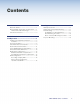
Contents Introduction............................................. 1 Mounting................................................17 About this Guide............................................... 1 About the MTP Transmitters and Receivers...... 1 Twisted Pair Cable Advantages..................... 2 Transmission Distance...................................... 3 Tabletop Placement........................................ 17 Under Desk and Furniture Mounting............... 17 Rack Mounting........................
Introduction This section gives an overview of the user guide. This section also describes the MTP 15HD RS series of transmitters and receivers.
The RS-232 portion of the twisted pair link: •• Can be bidirectional in a one-receiver system; that is, the receiver can receive commands from the transmitter and pass RS-232 responses to the transmitter. •• Supports software flow control (XON, XOFF). NOTE: Hardware flow control is not supported. •• Supports full duplex and half duplex operation. •• Supports any baud rate (up to 38,400), data bits, parity, stop bits, and data format without configuration.
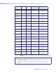
Transmission Distance The maximum distance is determined by the frequency and resolution of the signal that is input to the transmitter. The table on page 4 specifies the recommended maximum transmission distances and transmitter Pre-Peak switch positions (see item e on page 9) using Extron Enhanced Skew-Free AV UTP cable or CAT 5, 5e, or 6 cable, terminated with RJ-45 connectors.
Video Format Pre-Peak Pre-Peak Off On Composite, S-video, Component Max. Distance (High Quality) Max.
Installation and Operation This section provides information on: •• Installation and Operation Overview •• Front Panel Features •• Transmitter Rear Panel Features •• Receiver Rear Panel Features •• Power Supply Wiring and Grounding •• Twisted Pair Cable Termination •• Skew Delay Compensation •• EDID Configuration Installation and Operation Overview Follow the steps below to properly install and operate any of the Extron MTP 15HD RS transmitters and receivers.
Front Panel Features See figure 2 to identify the front panel features on the transmitter and receiver. MTP T 15HD RS transmitter EDID SELECT 50 Hz ON 1 RECORD 60 Hz 2 3 MTP SERIES SPARE 4 5 H SYNC + V SYNC + S VIDEO END UNIT BI-232 MTP RL 15HD RS receiver RGB PEAKING LEVEL ON 1 1 2 3 4 5 MTP SERIES 6 11 7 DELAY RED SELECT 1 GREEN BLUE LEVEL RGB PEAKING H SYNC + V SYNC + S VIDEO END UNIT BI-232 MTP RL 15HD RS SEQ receiver ON ADJUST 1 2 3 4 5 MTP SERIES 8 Figure 2.
d Vertical frequency DIP switch — The first DIP switch selects the vertical frequency for the pre-programmed EDID. When switched to Off (default position), the EDID selected by the rotary positions 1 through E are based on 60 Hz. When switched to On, they are based on 50 Hz. The second DIP switch, marked Spare, is not used.
j Delay (skew adjustment) control (SEQ model only) — This control delays the selected red, green, or blue video signal by up to 62 nanoseconds. The delay is applied in incremental, 2-nanosecond steps. Rotate the control counterclockwise to reduce the delay or clockwise to increase the delay. NOTES: • The control turns smoothly; it does not have mechanical steps or high and low limit stops. • Watch the displayed image to observe the steps of delay.
Transmitter Rear Panel Features Figure 3 shows the rear of an MTP T 15HD RS transmitter. 4 MTP T 15HD RS RS-232 PRE-PEAK Tx Rx G POWER 12V 0.5A MAX ON INPUT MONITOR 2 3 1 Figure 3. OFF OUTPUT 5 6 Transmitter Rear Panel NOTE: Control signal ground pins may be labeled as or “G”. Audio ground pins may be labeled as or . The wiring and function are the same, whichever way your product is labeled.
e Pre-Peak switch — The Pre-Peak switch alters the twisted pair signal output to correct for long cable runs (see the table on page 4 for suggested switch settings based on the transmitted video format and transmission distance). NOTES: • The length of the exposed wires in the stripping process is critical. The ideal length is 3/16 inches (5 mm). If the exposed section is longer, the exposed wires may touch, causing a short circuit between them.
Receiver Rear Panel Features Figure 6 shows an MTP RL 15HD RS receiver. M TP R L 15H D R S POWER 12V 0.5A MAX INPUT OUTPUTS BUFFERED OUTPUT RS-232 3 OUTPUT 1 2 Figure 6. 3 Tx Rx G 4 Receiver Rear Panel NOTE: Control signal ground pins may be labeled as or “G”. Audio ground pins may be labeled as or . The wiring and function are the same, whichever way your product is labeled.
Power Supply Wiring and Grounding Figure 7 shows how to wire and ground the connector. ATTENTION: Potential damage to property. • Power supply voltage polarity is critical. Incorrect voltage polarity can damage the power supply and the transmitter or receiver. Identify the power cord negative lead by the ridges on the side of the cord. • To verify the polarity before connection, plug in the power supply with no load and check the output with a voltmeter.
ATTENTION: Potential damage to property. • This product is intended to be supplied by a Listed Power Unit marked "Class 2" or "LPS", rated 12 VDC, maximum 1.0 A. Always use a power supply supplied or specified by Extron. Use of an unauthorized power supply voids all regulatory compliance certification and may cause damage to the supply and the end product.
Twisted Pair Cable Termination Figure 8 details the recommended termination of twisted pair cables with RJ-45 connectors in accordance with the TIA/EIA T568A or TIA/EIA T568B wiring standards. You can use either standard with CAT 5, 5e, and 6 cable, but ensure that you use the same standard on both ends of the cable. Pins: 12345678 Pin Insert Twisted Pair Wires RJ-45 Connector Figure 8. TIA/EIA T 568 A Wire color TIA/EIA T 568 B Wire color Signal 1 White-green White-orange Red/V.
Skew Delay Compensation CAT 5, 5e, and 6 cable can lead to registration errors between the red, green, and blue video signals. Pair skew can be measured with test equipment or identified by viewing a crosshatch test pattern with a critical eye to determine if either the red, green, or blue video image leads (appears to the left of) the other two video images. NOTE: Unless the twisted pair cable is changed, the skew adjustment should need to be made only once, during installation.
EDID Configuration The MTP 15HD RS transmitter can either record EDID from a display device, or a pre-programmed EDID can be selected using the rotary and DIP switches. Recording a Display EDID 1. Turn the rotary switch to position 0. NOTE: The vertical frequency DIP switch has no effect in this mode. 2. Connect the display device to the local monitor output connector. NOTE: The MTP 15HD transmitter should be supplying the necessary 5 VDC to power on the display.
Mounting This section outlines the various mounting options available for the MTP 15HD RS Series transmitters and receivers: •• Tabletop Placement •• Under-Desk and Furniture Mounting •• Rack Mounting •• Projector Mounting Tabletop Placement Attach the four provided rubber feet to the bottom of the unit and place it in any convenient location. Under Desk and Furniture Mounting Mount the unit under a desk or podium using an optional Extron under desk mounting kit (see www.extron.com).
Rack Mounting Procedure These units can be mounted an optional rack systems listed on the website (see www.extron.com). To mount the unit on a rack shelf, follow the instructions provided with the shelf accessories. Back of the Rack Mounting Procedure The MTP can be mounted to the rear of a rack using an optional back of rack mounting kit. (see www.extron.com). The kit allows the product to be vertically mounted to the front or rear rack supports and facing either towards the front or the rear of the rack.
Extron Warranty Extron Electronics warrants this product against defects in materials and workmanship for a period of three years from the date of purchase.