MVX 128 A VGA Matrix Switcher 68-521-31 Rev.
Precautions Safety Instructions • English Warning This symbol is intended to alert the user of important operating and maintenance (servicing) instructions in the literature provided with the equipment. Power sources • This equipment should be operated only from the power source indicated on the product. This equipment is intended to be used with a main power system with a grounded (neutral) conductor. The third (grounding) pin is a safety feature, do not attempt to bypass or disable it.
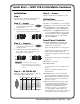
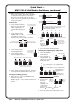
Quick Start — MVX 128 A VGA Matrix Switchers Step 5 — Power Installation Plug the switcher into a grounded AC source. Step 1 Turn off power to the input and output devices, and remove the power cords from them. Definitions Step 2 — Inputs Set of ties — An input tied to 2 or more outputs. b. Connect up to 12 high resolution video inputs to the 15-pin HD input connectors. Configuration — One or more ties or sets of ties.
Quick Start — MVX 128 A VGA Matrix Switchers, continued RGBHV and Audio buttons select/deselect video and/or audio. The Audio LED blinks to indicate audio breakaway. The Audio button also selects the audio level/adjust mode. See Viewing and adjusting the audio level in the next column. Save a preset Press and hold. 2 seconds Preset LED blinks. PRESET PRESET Recall a preset Create a tie 1. Press and release the Esc button to clear any input LEDs, output LEDs, or control LEDs that may be lit.
Table of Contents Chapter One • Introduction ...................................................................................................... 1-1 About this Manual..................................................................................................................... 1-2 About the Matrix Switchers ................................................................................................ 1-2 Definitions ...............................................................................
Table of Contents, cont’d Optimizing the Audio ............................................................................................................ 3-35 Troubleshooting ........................................................................................................................ 3-36 Configuration Worksheets ................................................................................................. 3-36 Worksheet example 1: System equipment ...........................................
1 Chapter One Introduction About this Manual About the Matrix Switchers Definitions Features PRELIMINARY MVX 128 A VGA Matrix Switchers
Introduction About this Manual This manual contains installation, configuration, and operating information for the Extron MVX 128 A 12-input by 8-output wideband computer video (VGA) and audio matrix switcher. About the MVX 128 A Matrix Switcher The MVX matrix switcher distributes any of 12 inputs to any combination of 8 outputs. The matrix switcher can route multiple input/output configurations simultaneously.
The MVX 128 A inputs and outputs VGA video on 15-pin HD connectors and audio on 3.5 mm, 5-pole captive screw terminals. The audio switching can be either linked with the video (audio follow) or be independent of the video (audio breakaway). Adjustable input audio gain and attenuation compensates for level differences between audio inputs. The matrix switcher can be remotely controlled via its RS-232/RS-422 port.
Introduction, cont’d Features Video — The switcher inputs and outputs RGBHV or RGBS (VGA) video on 15-pin HD connectors. It can also switch RGsB, RsGsBs, component/HDTV, S-video, or composite video. Bandwidth — The MVX switcher provides a minimum of 300 MHz (-3 dB) video bandwidth, fully loaded. Audio inputs — The switcher inputs and outputs balanced or unbalanced stereo audio on 3.5 mm, 5-pole captive screw terminals.
Upgradeable firmware — The firmware that controls all switcher operation can be upgraded in the field via RS-232/RS-422, without taking the switcher out of service. Firmware upgrades are available for download on the Extron Web site, www.extron.com, and can be installed using the Windows-based control program. Labeling — The Extron label software ships with every Extron matrix switcher.
PRELIMINARY Introduction, cont’d 1-6 MVX 128 A VGA Matrix Switchers • Introduction
2 Chapter Two Installation Mounting the Switcher Cabling and Rear Panel Views PRELIMINARY MVX 128 A VGA Matrix Switchers
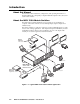
Installation Mounting the Switcher The MVX 128 A is housed in a rack-mountable, 2U high metal enclosure with mounting flanges for standard 19” racks. If desired, rack mount the switcher as follows: 1. Insert the switcher into the rack, aligning the holes in the mounting bracket with those in the rack. 2. Secure the switcher to the rack using the supplied bolts. Cabling and Rear Panel Views All connectors are on the rear panel. Figure 2-1 shows the rear panel of the MVX 128 A.
Audio connections By default, the audio ties follow the video ties. Audio breakaway, which can be activated via the front panel or under RS-232/RS-422 control, allows you to select from any one of the audio input sources and route it separately from its corresponding video source. See chapter 3, Operation, chapter 4, Programmer’s Guide, and chapter 5, Matrix Software for details. c Connections for balanced and unbalanced audio inputs — Each input has a 3.
Installation, cont’d d Connections for balanced and unbalanced audio outputs — These 3.5 mm, 5-pole captive screw connectors output the selected unamplified, line level audio. Connect audio devices, such as an audio amplifier or powered speakers. See figure 2-4 to properly wire an output connector. Tip Ring Sleeve (s) Tip Ring Tip See caution Sleeve Tip See caution Unbalanced Output Balanced Output Figure 2-4 — Captive screw connector wiring for audio output C Connect the sleeve to ground (Gnd).
Reset button f Reset button — The Reset button initiates two levels of reset to the matrix switcher. Press and hold the button while the switcher is running or RESET while you power up the switcher for different reset levels. See Reset button in chapter 3, Operation, for details.
PRELIMINARY Installation, cont’d 2-6 MVX 128 A VGA Matrix Switchers • Installation
3 Chapter Three Operation Front Panel Controls and Indicators Front Panel Operations Rear Panel Controls Optimizing the Audio Troubleshooting Configuration Worksheets PRELIMINARY MVX 128 A VGA Matrix Switchers
Operation Front Panel Controls and Indicators The front panel controls (figure 3-1) are grouped into two sets. The input and output buttons are grouped on the left side of the control panel. The control buttons and video/audio (I/O) selection buttons are grouped on the right side of the panel.
Input and output buttons a Input buttons and LEDs — The input buttons and LEDs have two primary functions (•) and two secondary (❏) functions: b • Select an input. • Identify the selected input. ❏ Select a preset. See Using global presets on page 3-21. ❏ Display the output volume level. See Viewing and adjusting the output volume on page 3-28. c • Select output(s). • Identify the selected output(s). ❏ Mute the output. See Muting and unmuting video and/or audio on page 3-18.
Operation, cont’d Control buttons d Enter button and LED — The Enter button and LED have three primary functions (•) and three secondary (❏) functions: • Saves changes that you make on the front panel. To create a simple configuration: Specify RGBHV, audio, or both (see I/O selection buttons [h] and [i]). Press the desired input button (a). Press the desired output button(s) (b). PRELIMINARY Press the Enter button. e 3-4 • Indicates that a potential tie has been created but not saved.
f View (<) button and LED — The View (<) button and LED have two primary functions (•) and six secondary (❏) functions: • Selects a View-Only mode that displays the current configuration. g • Indicates that View-Only mode is active. ❏ Decreases the audio level of the selected input. See Viewing and adjusting the input audio level on page 3-24. ❏ Indicates a negative (attenuation) audio level. See Viewing and adjusting the input audio level on page 3-24.
Operation, cont’d I/O controls You must specify video, audio, or both when you are creating or viewing a configuration. This is done with the RGBHV button (h) and Audio (i) buttons. PRELIMINARY h i 3-6 RGBHV button and LED — The RGBHV button and LED have two primary functions (•) and four secondary (❏) functions: • Selects and deselects video for a configuration that is being created or viewed. • Lights green to indicate that video is available for configuring or for viewing.
Front Panel Operations • Creating ties, sets of ties, and configurations • Changing a configuration • Viewing ties, sets of ties, and configurations • Muting and unmuting outputs • Saving a preset • Recalling a preset • Viewing and adjusting the output volume • Viewing and adjusting the input audio level • Locking the front panel • Performing front panel resets • Reading and setting the RS-232/RS-422 Remote port settings Power Apply power by connecting the power cord to an AC source.
Operation, cont’d Creating a configuration The current configuration can be changed using the front panel buttons. Change the current configuration as follows: 1. Press the Esc button to clear any input LEDs, output LEDs, or control LEDs that are lit. 2. Select to configure video, audio, or both by pressing the RGBHV button and/or Audio button. 3. Select the desired input and output(s) by pressing the input and output buttons.
Example 1: Creating a set of video and audio ties In the following example, input 5 is tied to outputs 3, 4, and 8. The steps show the front panel indications that result from your actions. N This example assumes that there are no ties in the current configuration. 1. Press and release the Esc button (figure 3-3). Press the Esc button to clear all selections. CONTROL 1 ENTER PRESET VIEW 1 = Blink once ESC The LED blinks once.
Operation, cont’d 4. Press and release the output 3, output 4, and output 8 buttons (figure 3-6). N The entire set of ties can be canceled at this point by pressing and releasing the Esc button. The Esc LED flashes once. Press and release the Output 3, Output 4, and Output 8 buttons. The buttons blink to indicate that the selected RGBHV and audio input will be tied to these outputs. ENTER PRESE 1 2 3 4 5 OUTPUTS 6 7 8 The Enter LED blinks to indicate the need to confirm the change.
Example 2: Adding a tie to a set of video and audio ties In the following example, a new video tie is added to the current configuration. The steps show the front panel indications that result from your action. N This example assumes that you have performed example 1. 1. Press and release the Esc button (figure 3-9). Press the Esc button to clear all selections. CONTROL 1 ENTER PRESET VIEW = Blink once 1 ESC The LED blinks once.
Operation, cont’d 5. Press and release the Enter button (figure 3-13). Press the Enter button to confirm the configuration change. The Enter LED and all input LEDs and output LEDs return to the unlit state. ENTER Figure 3-13 — Press the Enter button The current configuration (figure 3-14) is now: • Input 5 (video) is tied to output 1, output 3, output 4, and output 8 • Input 5 (audio) is tied to output 3, output 4, and output 8 PRELIMINARY Input 5 video tied to outputs 1, 3, 4, and 8.
Example 3: Removing a tie from a set of video and audio ties In the following example, an existing audio tie is removed from the current configuration. The steps show the front panel indications that result from your action. N This example assumes that you have performed example 1 and example 2. 1. Press and release the Esc button (figure 3-15). Press the Esc button to clear all selections. CONTROL 1 ENTER PRESET VIEW 1 = Blink once ESC The LED blinks once.
Operation, cont’d 4. Press and release the Output 4 button (figure 3-18). Press and release the Output 4 button. The LED blinks to indicate that the selected RGBHV output will be untied. ENTER PRESE 1 2 3 6 4 5 OUTPUTS The Enter LED blinks to indicate the need to confirm the change. Figure 3-18 — Deselect the output 5. Press and release the Enter button (figure 3-19). Press the Enter button to confirm the configuration change.
Viewing a configuration The current configuration can be viewed using the front panel buttons. The View-Only mode prevents inadvertent changes to the current configuration. View-Only mode also provides a way to mute video and audio outputs (see Muting and unmuting video and/or audio on page 3-18). 1. Press the Esc button to clear any input LEDs, output LEDs, or control LEDs that are lit. 2. Press and release the View button. All of the LEDs for outputs that are not tied light. 3.
Operation, cont’d To select both video and audio for viewing, if necessary, press and release the RGBHV button and the Audio button (figure 3-22). 3. I/O In this example, the Audio LED blinks to indicate audio breakaway (assuming you have performed example 1, 2, and 3). RGBHV AUDIO Press the RGBHV button to toggle on and off. The LED lights when selected. Press the Audio button to toggle on and off. The LED lights or blinks when selected.
Press and release the RGBHV button to deselect RGBHV (figure 3-24). 5. I/O The output buttons for outputs that are tied to input 5 light to indicate audio ties (audio breakaway). RGBHV AUDIO Press the RGBHV The Audio LED remains button to delesect it. lit to indicate that only The LED is unlit audio is selected. when deselected. 2 3 4 5 OUTPUTS 6 7 8 The output buttons for outputs that are not tied to input 5 are unlit.
Operation, cont’d Muting and unmuting video and/or audio Individual outputs can be muted or unmuted as follows: 1. Press the Esc button to clear any input LEDs, output LEDs, or control LEDs that are lit. 2. Press and release the View button. 3. Select video, audio, or both to mute or unmute by pressing the RGBHV button and/or the Audio button. 4. One at a time, press and hold the output button(s) for the desired output(s) for approximately 2 seconds.
3. To select both video and audio for viewing and muting, if necessary, press and release the RGBHV button and the Audio button (figure 3-28). N This example shows the indications that the front panel displays if example 1, example 2, and example 3 have been completed. I/O In this example, the Audio LED blinks to indicate audio breakaway (assuming you have performed example 1, 2, and 3). RGBHV AUDIO Press the RGBHV button to toggle on and off. The LED lights when selected.
Operation, cont’d 5. Press and hold the Output 3 button and the Output 4 button (figure 3-30) for approximately 2 seconds until the LEDs light steadily. The output 3 and output 4 video and audio signals are unmuted. Press and hold the Output 3 and Output 4 button. 3 4 5 OUTPUTS 2 seconds 3 4 5 OUTPUTS The LEDs stop blinking and light to indicate that the RGBHV and audio outputs are unmuted. Release the button.
Using global presets N • Only the audio and video ties are stored and recalled; audio gain settings are not saved, and they do not change when a preset is recalled. • Presets cannot be viewed from the front panel unless recalled as the current configuration. Presets can be viewed using Extron’s Windows-based control program. See Chapter 5, Matrix Software, for more details. • The current configuration and all presets are stored in non-volatile memory.
Operation, cont’d 2. Press and hold the Preset button for approximately 2 seconds until the Preset LED blinks (figure 3-34). All input and output LEDs with assigned presets light. If you then save the configuration to a lit preset number, the configuration data at that preset location will be overwritten. Lit Unlit Press and hold the Preset button until the (Preset Assigned) (Preset Unassigned) Preset LED blinks. Release the Preset button.
Example 7: Recalling a preset The following steps show an example in which a preset is recalled to become the current configuration. The steps show the front panel indications that result from your actions. 1. Press and release the Esc button (figure 3-37). Press the Esc button to clear all selections. CONTROL 1 ENTER PRESET VIEW = Blink once 1 ESC The LED blinks once. Figure 3-37 — Clear all selections 2. Press and release the Preset button (figure 3-38).
Operation, cont’d 4. Press and release the Enter button (figure 3-40). The configuration stored in memory location 13 is now the current configuration and can be viewed in the View-Only mode (see example 4). Press the Enter button to recall the preset. CONTROL ENTER PRESET VIEW ESC All input LEDs return to the unlit state. The Enter and Preset LEDs return to the unlit state.
4. 5. Press and release an input button to select an input. The output LEDs display the audio level for the selected input and the Esc (>) and View (<) LED display the polarity (gain [+] or attenuation [–]). Each output LED indicates 1 dB when blinking slowly, 2 dB when blinking quickly, and 3 dB when lit. See the table at right.
Operation, cont’d Example 10: Viewing and adjusting an input audio level In the following example, an audio level is viewed and adjusted. The steps show the front panel indications that result from your action. 1. Press and release the Esc button (figure 3-42). Press the Esc button to clear all selections. CONTROL 1 ENTER PRESET VIEW 1 = Blink once ESC The LED blinks once. Figure 3-42 — Clear all selections 2.
4. Press and release the View (<) button once (figure 3-45) to decrease the input audio level by 1 dB. Press and release the View (<) button several more times (figure 3-45) to decrease the input audio level by 1 dB per button push. Note the output button indication changes that occur each time the View (<) button is pressed. Figure 3-45 shows the result of pressing the View (<) button a total of nine times. Note that the level is now displayed in red to indicate a negative level.
Operation, cont’d Viewing and adjusting the output volume The audio level of each output can be displayed and adjusted through a range of 100% (no attenuation) to 0% (maximum [98 dB] attenuation). The audio level can be adjusted from the front panel or under RS-232/RS-422 control. 1. Press the Esc button to clear any input LEDs, output LEDs, or control LEDs that are lit. 2. To enter the Audio mode, press and hold the Audio button until the LED begins to blink, then release the button. 3.
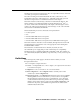
N This section is a detailed look at reading the output volume display on the matrix switcher’s front panel. If you do not need to read the exact value of the volume setting, skip this section. There are 65 steps of volume attenuation, with 1 dB per step (button push), except for 0-to-1, which is 35 dB. At maximum attenuation, no input LEDs are lit, 98 dB of attenuation is applied, and the audio output is effectively muted.
Operation, cont’d When all input LEDs are lit, the audio output is 100% of the audio input level. Another way to view the volume level is to think in terms of the attenuation that is applied to the output. Attenuation reduction is indicated by the lit or blinking input LEDs: when fewer input LEDs are lit, attenuation is greater (and the volume is less). • At minimum volume, all input LEDs are unlit and 98 dB of attenuation is applied to the output. The audio output is effectively muted.
Press and release the Output 1 button (figure 3-49). 3. The input LEDs display the selected output's audio volume level. In this example, the lit input buttons indicate 40 to 41.5 percent of the applied audio input. The unlit input buttons indicate an audio volume attenuation of 39 dB to 40 dB. Press and release the Output 1 button. The LED lights. –39 dB attenuation, 41.
Operation, cont’d Locking out the front panel (Executive mode) The front panel lock (Executive mode) limits the operation of the matrix switcher from the front panel. When the switcher is locked, all of the front panel functions are disabled except for the View-Only mode functions. See Viewing a configuration on page 3-15. Other than in View-Only mode, if the user pushes a front panel output button when the switcher is locked, the RGBHV and Audio LEDs flash twice and return to their previous state.
Selecting the RS-232/RS-422 protocol and baud rate The switcher can support either RS-232 or RS-422 serial communication protocol, and operate at 9600, 19200, 38400, and 115200 baud rates. The settings of these variables can be viewed and changed from the front panel. View and configure the switcher’s serial communications settings as follows: 1. To enter Serial Port Configuration mode, simultaneously press and hold all Control buttons (Enter, Preset, View, and Esc) (figure 3-54).
Operation, cont’d Press and release an input or output button to exit the Serial Port Configuration mode (figure 3-56). 4. Press and release an input or output button. CONTROL ENTER PRESET VIEW 5 I/O ESC RGBHV AUDIO All Control LEDs return to the unlit state. Each I/O LED returns to its previous state. Figure 3-56 — Exit Serial Port Configuration mode N The switcher requires some time to save the new serial port settings.
Performing a hard reset from the rear panel The hard reset function restores the switcher to the original factory default settings. All user files and settings are maintained. Perform a hard reset as follows: 1. If necessary, turn off power to the switcher. 2. Press and hold the Reset button on the rear panel while you apply AC power to the switcher (figure 3-58). Press and hold the Reset button while you apply power to the switcher. RESET Power RESET Release the Reset button.
Operation, cont’d Troubleshooting This section gives recommendations on what to do if you have problems operating the switcher and describes an actual image problem that Extron has encountered. 1. Ensure that all devices are plugged in and powered on. The switcher is receiving power if one of the front panel I/O LEDs is lit. 2. Check to see if one or more outputs are muted. 3. Ensure an active input is selected for output on the switcher. 4. Ensure that the proper signal format is supplied. 5.
Worksheet example 2: Daily configuration Figure 3-60 continues from worksheet example 1 by showing the video and audio ties that make up the configuration of preset 1. Solid ink lines show video ties and dashed pencil lines show the audio ties.
Operation, cont’d Worksheet example 3: Test configuration The A/V system in our fictional organization needs to be fine tuned on a regular basis. Figure 3-61 shows a typical test configuration, with an Extron video test generator (input 12) generating a test pattern to all monitors (outputs 1, 2, 3, 4, and 8). Sound checks are run from the CD player (input 5) to all audio systems (outputs 1, 2, 3, 4, and 8).
MVX 128 A VGA Matrix Switchers • Operation 3-39 2 2 Title: 3 3 5 5 Output destinations 4 4 Video: 6 6 7 7 8 8 Audio: PRELIMINARY Configuration worksheet Fill in the preset number and use colors, or dashes, etc. to make connecting lines. Indicate if the configuration is for video, audio, or both.
PRELIMINARY Operation, cont’d 3-40 MVX 128 A VGA Matrix Switchers • Operation
4 Chapter Four Programmer’s Guide Host-to-Switcher Instructions Switcher-Initiated Messages Switcher Error Responses Using the Command/Response Tables Command/Response Table for SIS Commands Special Characters PRELIMINARY MVX 128 A VGA Matrix Switchers
Programmer’s Guide 1 5 6 9 RS232/RS422 REMOTE The switcher’s rear panel Remote 9-pin D female connector (figure 4-1) can be connected to the RS-232 or RS-422 serial port output of a host device such as a computer running the HyperTerminal utility, an RS-232 capable PDA, or a control system. This connection makes software control of the switcher possible.
Outnn Volxx] The switcher initiates the Vol message when a front panel output audio volume change has occurred. “nn” is the output number and “xx” is the volume level. Vmtnn*x] The switcher initiates the Vmt message when a video output mute is toggled on or off from the front panel. “nn” is the output number and “x” is the mute status: 1 = on, 0 = off. Amtnn*x] The switcher initiates the Amt message when an audio output mute is toggled on or off from the front panel.
Programmer’s Guide, cont’d Command/Response Table for SIS Commands Symbol definitions ] } • E X! X@ X# X$ X% X^ X& PRELIMINARY X* X( X1) = CR/LF (carriage return/line feed) (hex 0D 0A) = Carriage return (no line feed, hex 0D)) = Space character = Escape key (hex 1B) = Input number 01 – 12 = Input number (for tie) 00 – 12 (00 = untied) = Output number 01 – 08 = Numeric dB value –18 to +24 (45 steps of gain or attenuation) = Audio gain 0 – 24 (1 dB/step) = Audio attenuation 1 – 18 (1 dB/step) =
Command/response table for SIS commands Command ASCII command Response (host to switcher) (switcher to host) Additional description Create ties N • Commands can be entered back-to-back, with no spaces. For example: 1*1!02*02&003*003%4*8$. • The quick multiple tie and tie input to all output commands activate all I/O switches simultaneously. • The matrix switchers support 1-, 2-, and 3-digit numeric entries (1*1, 02*02, or 001*001).
Programmer’s Guide, cont’d Command/response table for SIS commands (continued) Command ASCII command Response (host to switcher) (switcher to host) Additional description RGB mute X#*1B VmtX#*1] Mute output X# RGB (video off). RGB unmute X#*0B VmtX#*0] X*] Vmt1] Vmt0] Unmute output X# RGB (video on). 1 = mute on, 0 = mute off. Video mute commands Read RGB mute X#B Global RGB mute 1*B Global RGB unmute 0*B Mute all RGB outputs. Unmute all RGB outputs.
X7 value dB of attenuation Output volume 00 98 0% 01 63 02 X7 value dB of attenuation Output volume X7 value dB of attenuation Output volume 5.5% 23 41 38.5% 45 19 71.5% 62 7% 24 40 40% 46 18 73% 03 61 8.5% 25 39 41.5% 47 17 74.5% 04 60 10% 26 38 43% 48 16 76% 05 59 11.5% 27 37 44.5% 49 15 77.5% 06 58 13% 28 36 46% 50 14 79% 07 57 14.5% 29 35 47.5% 51 13 80.5% 08 56 16% 30 34 49% 52 12 82% 09 55 17.5% 31 33 50.
Programmer’s Guide, cont’d Command/response table for SIS commands (continued) Command ASCII command Response (host to switcher) (switcher to host) EX(,X1#NG} E1,Security 1NG} NmgX(,X2@] Additional description Names Write global preset name Example: Nmg01,Security 1] EX(NG} X1#] E2NG} Security 2] N • If a preset is unassigned, the X2# displays [unassigned]. • If a global preset is saved, but not yet named, the default name is Preset X1!.
Command/response table for SIS commands (continued) Command ASCII command Response (host to switcher) (switcher to host) Additional description Reset global presets and names EZG} Zpg] Clear all global presets and their names. Reset one global preset EX(ZG} EZA} ZpgX(] Reset audio input levels Rest audio output levels EZV} Zpv] Reset all mutes EZZ} Zpz] Reset flash EZFFF} Zpf] Reset whole switcher EZXXX} Zpx] Absolute reset EZQQQ} Zpq] Clear global preset X(.
Programmer’s Guide, cont’d Command/response table for SIS commands (continued) Command ASCII command Response (host to switcher) (switcher to host) Additional description View ties, gain, volume, mutes, and presets (continued) View video global preset configuration Command description: Response description: EX(*1*1VC} X@1•X@2•...•X@16•Vid] Show preset X(’s video configuration. Show the input tied to 16 sequential outputs (12 are present on this model), starting from output 1.
Command/response table for SIS commands (continued) Command ASCII command Response (host to switcher) (switcher to host) I V12X08•A12X08] Additional description Information requests 60-799-01] N There are two separate sets of Extron firmware that the switcher can report on: the controller firmware, which is the overall control firmware; and the latest optional Extron firmware update, which is available at www.Extron.com. Query controller firmware Q X1!] version Example: Q The factory-installed 1.
PRELIMINARY Programmer’s Guide, cont’d 4-12 MVX 128 A VGA Matrix Switchers • Programmer’s Guide
5 Chapter Five Matrix Software Matrix Switchers Control Program Button Label Generator Program PRELIMINARY MVX 128 A VGA Matrix Switchers
Matrix Software Two software programs accompany the MVX 128 A switcher: • The Extron Matrix Switcher Control Program, which communicates with the switcher via the RS-232/RS-422 port, provides an easy way to set up ties and sets of ties. • The Extron Button-Label Generator, which allows you to design and print labels for the MVX 128 A front panel buttons. Both programs are compatible with Windows 95/98, Windows NT, Windows ME, Windows 2000, and Windows XP.
Using the software Many items found in the Matrix Switcher Control Program are also accessible via front panel controls (see chapter 3, Operation) and under SIS control (see chapter 4, Programmer’s Guide). The Matrix Switcher+ Help Program provides information on settings and on how to use the control program itself. 1. To run the Matrix Switcher Control Program, double-click on the Matrix Switcher Control Program icon (shown at right) in the Extron Electronics group or folder.
Matrix Software, cont’d PRELIMINARY 3. The Extron Matrix Switcher Control Program window (figure 5-2 and figure 5-3) appears. The window displays the current configuration of the attached matrix.
• To set up audio in follow mode (audio and video have the same tie configuration), select the Follow box at the bottom of the window. To set up audio in breakaway mode (audio and video have different tie configurations), deselect the Follow box. • To make the control program easier to use, assign a device icon to each input and output. Click on a box that represents an input or output, and drag the desired icon onto the box from the icon palette that appears.
Matrix Software, cont’d 5. Navigate to the folder where you saved the firmware upgrade file. Select the file. N Valid firmware files must have the file extension .S19. Any other file extension is not a firmware upgrade. N The original factory-installed firmware is permanently available on the MVX 128 A switcher. If the attempted firmware upload fails for any reason, the switcher reverts to the factory-installed firmware. PRELIMINARY 6. Click the Open button.
Windows buttons, drop boxes, and trashcan The buttons, drop boxes, and trash can on the right side of the program window perform the following functions: Power — Unavailable for MVX 128 A switchers, because the switcher power cannot be controlled via software. Executive mode — Allows you to lock out front panel operations, except for the view-only mode functions. Presets menu — Displays a list of up to 32 global presets.
Matrix Software, cont’d Tools menu Assign device icons — Displays the complete set of input and output device icons. You can drag any of these icons to the input and output boxes. Edit device palette — Allows you to add your own device icon graphics. Audio-Input gain settings — Displays the audio gain level setting for a single input or for all inputs and allows you to change it.
Name presets — Allows you to assign a name to each of the 32 memory presets. N Preset names are limited to 12 upper- and lower-case alphanumeric characters, space, and the _ : = and / characters. N The following characters are invalid in preset names: + ~ , @ = ‘ [ ] { } < > ’ “ ; : | \ and ?. Show RS-232 strings — Displays the ASCII commands that are used by the current configuration. You can refer to these for RS-232 programming.
Matrix Software, cont’d Icons in I/O boxes — Erases any numbers in the I/O boxes in the Control Program window (figure 5-3). You can place icons in the boxes. Numbers in I/O boxes — Erases any icons in the I/O boxes in the Control Program window and fills each box with the associated input or output number.
A Appendix A Specifications, Part Numbers, Accessories Specifications Part Numbers and Accessories Button Labels PRELIMINARY MVX 128 A VGA Matrix Switchers
Specifications, Part Numbers, Accessories Specifications Video Routing ........................................... 12 x 8 matrix Gain ................................................. Unity Bandwidth ...................................... >300 MHz (-3 dB) , fully loaded 0 - 10 MHz ..................no more than +0.1 dB to -0.1 dB 0 - 130 MHz ................no more than +0.8 dB to -0.8 dB Crosstalk .........................................
Audio Routing ........................................... Gain ................................................. Frequency response ...................... THD + Noise .................................. S/N .................................................. Crosstalk ......................................... Stereo channel separation ............ CMRR.............................................. 12 x 8 stereo matrix Unbalanced output: -6 dB; balanced output 0 dB 20 Hz to 20 kHz, ±0.05 dB 0.
Specifications, Part Numbers, Accessories, cont’d General PRELIMINARY Power .............................................. 100 VAC to 240 VAC, 50/60 Hz, 30 watts, internal, autoswitchable Temperature/humidity ................ Storage: -40 to +158 °F (-40 to +70 °C) / 10% to 90%, noncondensing Operating: +32 to +113 °F (0 to +45 °C) / 10% to 90%, noncondensing Rack mount .................................... Yes, with included brackets Enclosure type ...............................
Part Numbers and Accessories Included parts These items are included in each order for a MVX 128 A matrix switcher: Included parts MVX 128 A Replacement part number 60-799-01 Tweeker (small screwdriver) MVX 128 A user’s manual Captive screw audio connectors (20) 10-319-10 Matrix Switchers Control Program and Button-Label Generator Accessories Adapters, power supplies, labels PRELIMINARY These items can be ordered separately: Part number MKP 1000 remote keypad Black 60-239-02 White 60-239-03 RAL9
Specifications, Part Numbers, Accessories, cont’d Cables Male-to-female VGA molded connector cables 26-112-17 VGA 6’ MHR, 6’ (1.8 m) 26-112-15 VGA 15’ MHR, 15’ (4.5 m) 26-112-01 VGA 25’ MHR, 25’ (7.6 m) 26-112-05 VGA 35’ MHR, 35’ (10.6 m) 26-112-28 VGA 50’ MHR, 50’ (15.2 m) 26-112-29 VGA 75’ MHR, 75’ (22.8 m) 26-112-30 VGA 100’ MHR, 100’ (30.4 m) 26-112-31 PRELIMINARY Male-to-female VGA backshell connector cables Part number VGA 3’ MHR, 3’ (0.9 m) 26-112-35 VGA 6’ MHR, 6’ (1.
Button Labels Figure A-1 provides 12-button strips of blank button labels. Feel free to photocopy them or cut them out of the manual, write button information in each button area as desired, and put them in the switcher’s label window. For 8-button strips, use scissors to trim the blank to the appropriate length.
PRELIMINARY Specifications, Part Numbers, Accessories, cont’d A-8 MVX 128 A VGA Matrix Switchers • Specifications, Part Numbers, Accessories
FCC Class A Notice Note: This equipment has been tested and found to comply with the limits for a Class A digital device, pursuant to part 15 of the FCC Rules. These limits are designed to provide reasonable protection against harmful interference when the equipment is operated in a commercial environment. This equipment generates, uses and can radiate radio frequency energy and, if not installed and used in accordance with the instruction manual, may cause harmful interference to radio communications.
www.extron.com Extron Electronics, USA Extron Electronics, Europe Extron Electronics, Asia Extron Electronics, Japan 1230 South Lewis Street Anaheim, CA 92805 USA 714.491.1500 Fax 714.491.1517 Beeldschermweg 6C 3821 AH Amersfoort The Netherlands +31.33.453.4040 Fax +31.33.453.4050 135 Joo Seng Road, #04-01 PM Industrial Building Singapore 368363 +65.6383.4400 Fax +65.6383.4664 Kyodo Building 16 Ichibancho Chiyoda-ku, Tokyo 102-0082 Japan +81.3.3511.7655 Fax +81.3.3511.