User Guide Matrix Switchers MVX 44 / 48 / 84 / 88 Series VGA Matrix Switchers 68-877-01 Rev.
Safety Instructions • English Warning This symbol is intended to alert the user of important operating and maintenance (servicing) instructions in the literature provided with the equipment. Power sources • This equipment should be operated only from the power source indicated on the product. This equipment is intended to be used with a main power system with a grounded (neutral) conductor. The third (grounding) pin is a safety feature, do not attempt to bypass or disable it.
FCC Class A Notice This equipment has been tested and found to comply with the limits for a Class A digital device, pursuant to part 15 of the FCC Rules. Operation is subject to the following two conditions: This device may not cause harmful interference. 1. This device must accept any interference received, including interference that may cause undesired operation.
Conventions Used in this Guide In this user guide, the following are used: NOTE: A note draws attention to important information. TIP: A tip provides a suggestion to make working with the application easier. CAUTION: WARNING: A caution indicates a potential hazard to equipment or data. A warning warns of things or actions that might cause injury, death, or other severe consequences.
Contents Introduction............................................. 1 Remote Operation.................................. 36 About this Guide.............................................. 1 About the Switchers......................................... 1 Features............................................................ 2 IR Remote Control.......................................... 36 Simple Instruction Set Control......................... 37 Host-to-Switcher Instructions......................
MVX 44 / 48 / 84 / 88 VGA Matrix Switchers • Contents vi
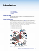
Introduction • About this Guide • About the Switchers • Features About this Guide This guide contains installation, configuration, and operating information for the Extron® MVX VGA Matrix Switchers. About the Switchers The Extron MVX Series VGA matrix switchers (see figure 1) is a family of computer video matrix switchers that distribute any VGA or component/HDTV video (or other high resolution video) and audio input to any combination of outputs.
NOTE: The switchers can also distribute S-video and composite video with applicable adapters. The MVX switcher can be locally controlled from the front panel or remotely controlled via its rear panel RS-232 serial port or an optional IR 501 Small Matrix Infrared (IR) Remote Control (part number 70-336-01). Features Video — These switchers input and output VGA – UXGA RGBHV, RGBS, RGsB, RsGsBs video, or component/HDTV signals on 15-pin HD female connectors. Bandwidth — Bandwidth is 300 MHz (–3 dB).
Upgradeable firmware — The firmware that controls the operation of the switcher can be upgraded in the field via the RS-232 port, without taking the switcher out of service. Firmware upgrades are available for download on the Extron website, www.extron.com, and they can be installed using the Windows-based control program. Global memory presets — Sixteen global memory presets are a time-saving feature that lets you set up and store input/output configurations in advance.
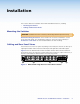
Installation This sections details the installation of the MVX VGA Matrix Switchers, including: • Mounting the Switcher • Cabling and Rear Panel Views Mounting the Switcher CAUTION: Installation and service must be performed by authorized personnel only. Detailed mounting instructions can be found in the “Reference Information“ section at the end of this guide. The 1U high matrix switchers can be placed on a tabletop or mounted on a rack shelf. Use the included hardware for rack mounting.
Video and Audio Input Connections a RGB video inputs — Connect the analog computer-video sources to these 15-pin HD female connectors. NOTE: 1 Most laptop or notebook computers have an external video port, but they require special commands to output the video to that connector. Also, a laptop screen shuts off once that port is activated.
NOTES: • The length of exposed wires is critical. The ideal length is 3/16 inch (5 mm). • If the stripped section of wire is longer than 3/16 inch, the exposed wires may touch, causing a short circuit. • If the stripped section of wire is shorter than 3/16 inch, wires can be easily pulled out even if tightly fastened by the captive screws. • Figure 4 on the preceding page identifies the tip, ring, and sleeve. A mono audio connector consists of the tip and sleeve.
Power Connection e AC power connector — Plug a standard IEC power cord into this connector to connect the switcher to a 100 VAC to 240 VAC, 50 or 60 Hz power source.
Operation This section describes the front panel operation of the MVX VGA Matrix Switcher, including: • Front Panel Controls and Indicators • Operations • Optimizing the Audio • Troubleshooting • Worksheets Front Panel Controls and Indicators The number of input and output buttons and LEDs that each MVX Series VGA matrix switcher provides varies with the number of inputs and outputs. Figure 6 shows the front panel of an 8-input, 8-output video and audio switcher.
Infrared Sensor and Power/audio/data LED a Infrared remote sensor — This sensor receives infrared (IR) signals from the optional IR 501 small matrix universal remote control. The IR remote control must be pointed within 30 degrees of this sensor for best results. Operation of the IR 501 remote control is described in the IR 501 Small Matrix IR Remote Control User Guide. NOTE: b Keep the switcher out of bright light to prevent interference with the IR signals from the IR 501 remote control.
Control Buttons and LEDs e f Enter button — The Enter button saves changes when you set up a new configuration. To create a simple configuration: • Specify video, audio, or both (see controls [item g] and [item h]). • Press the desired input button (item c). • Press one or more desired output buttons (item d). • Press the Enter button. Preset button and LED — The Preset button activates either Save Preset mode or Recall Preset mode. Save Preset mode saves a configuration as a preset.
i Audio Setup LED — The Audio Setup LED lights red to indicate that the switcher is in Audio Setup mode. See “Adjusting Input Audio Gain and Attenuation” on page 23. Alternate IR error function — The Audio Setup LED also indicates errors when you use an IR 501 small matrix remote control. The LED lights for approximately 1 second when the switcher receives an unexpected or out-of-sequence IR command from the remote control. The switcher otherwise ignores the command.
Operations The following paragraphs define matrix switcher terms and then detail the power-up process and then provide sample procedures for creating ties, sets of ties, and configurations; changing a configuration; viewing ties, sets of ties, and configurations; saving a preset; recalling a preset; viewing and adjusting the audio level; and selecting the front panel security lockout.
Creating a Set of Ties You can create a set of ties, changing the current configuration, by using the front panel buttons. Change the current configuration as follows: 1. Select video, audio, or both to configure by pressing the I/O button as necessary. 2. Select the desired input and one or more outputs by pressing the input and output buttons. 3. Press and release the Enter button. 4. Repeat steps 1 through 3 to create additional ties until the desired configuration is complete.
3. Select the outputs: Press and release the output 3, output 4, and output 8 buttons. NOTE: The entire set of ties can be canceled at this point by by waiting for the 5-second input/output button timeout to occur. Press and release the Output 3, 4, and 8 buttons. OUTPUTS 2 1 4 3 5 6 7 8 The LEDs blink to indicate that the selected input will be tied to these outputs. 4. Confirm the change: Press and release the Enter button. Press the Enter button to confirm the configuration change.
Example 2: Add a video tie to a set of video and audio ties In the following example, a new video tie is added to the current configuration. The example shows the front panel indications that result from your actions. NOTE: This example assumes that you have performed example 1. 1. Select video only for the tie: If necessary, press and release the I/O button to cycle through the selections until the only the Video LED lights. Press the button. I/O The video LED lights when video is selected.
Example 3: Remove a tie from a set of ties In the following example, an existing tie is removed from the current configuration. The example shows the front panel indications that result from your actions. NOTE: This example assumes that you have performed example 1 and example 2. 1. Select audio only for the tie: If necessary, press and release the I/O button to cycle through the selections until the only the Audio LED lights. Press the button. I/O The video LED is off when video is deselected.
Viewing the Configuration The current configuration (all active ties) can be viewed using the front panel buttons as follows: 1. Select video, audio, or both to view by pressing the I/O button. 2. Press and release an input or output button. a. Press and release an input button — All of the buttons for outputs that are tied to the selected input light. If the Audio LED is flashing, it indicates that there are audio-only ties (audio breakaway).
2. Select an input: Press and release the input 5 button. Press and release the Input 5 button. INPUTS 1 2 3 4 5 6 7 8 The Input 5 LED lights to indicate that input 5 is selected. OUTPUTS 1 2 3 4 5 6 7 8 The Output 1, Output 3, Output 4, and Output 8 LEDs light to indicate the video ties created in examples 1, 2, and 3. I/O The audio LED blinks to indicate that for at least one tie audio is routed from a different source or not tied at all (audio breakaway). VID +dB AUD -dB 3.
Example 5: View ties by selecting outputs In the following example, the video and audio, audio-only, and video-only ties in the current configuration are viewed by selecting various outputs. The example shows the front panel indications that result from your actions. 1. Select video and audio for viewing: If necessary, press and release the I/O button to cycle through the selections until the both LEDs light. Press the button. I/O The video LED lights when video is selected.
4. Deselect video and select audio: Press and release the I/O button. Press the button. OUTPUTS I/O The video LED is off when video is deselected. The audio LED lights when audio is selected. VID +dB AUD -dB 2 1 3 4 5 6 7 8 The Output 3 LED lights to indicate that output 3 is selected and it is receiving audio. The source is indicated by the Input LED. The Output 8 LED also lights to indicate that output 8 is receiving audio from the indicated input.
INPUTS MVX 44 Preset OUTPUTS 1 2 3 4 1 2 3 4 1 2 3 4 5 6 7 8 1 2 3 4 1 2 3 4 5 6 7 8 1 2 3 4 5 6 7 8 9 10 11 12 1 2 3 4 5 6 7 8 1 2 3 4 1 2 3 4 5 6 7 8 9 10 11 12 1 2 3 4 5 6 7 8 1 2 3 4 5 6 7 8 1 2 3 4 5 6 7 8 9 12 11 12 13 14 15 16 INPUTS MVX 48 Preset OUTPUTS INPUTS MVX 84 Preset OUTPUTS INPUTS MVX 88 Preset OUTPUTS Figure 11.
Example 7: Recall a preset The following steps show an example in which a preset is recalled to become the current configuration. The example shows the front panel indications that result from your actions. 1. Select Recall Preset mode: Press and release the Preset button. Press and release the button. PRESET The LED lights to indicate Recall Preset mode. All input and output buttons with assigned presets light. If you then recall the configuration from an unlit preset number, all ties will be cleared.
Adjusting Input Audio Gain and Attenuation Switchers have input audio gain and attenuation adjustments. In Audio Setup mode, the audio level of each input can be adjusted through a range of –18 dB to +10 dB. This adjustment range ensures that there is no noticeable volume difference among sources. It also eliminates the need for separate preamps or attenuators when used with professional (higher line level) and consumer (lower line level) audio equipment (see figure 12).
By noting the status of these LEDs and counting the number of 1 dB steps you increase or decrease the audio level (step 4 and example 8, step 2a), you can determine the exact input gain or attenuation setting. b. The Power LED blinks to indicate the adjusted audio level (compared to the internal level, -10 dBV): • When the LED is lit most of the time, blinking off only occasionally, the level is too high. • When the LED is off most of the time, blinking on (lit) only occasionally, the level is too low.
2. Select an input: Press and release the Input 5 button. 10 6 3 0 3 + VU Press and release the Input 5 button. INPUTS 4 OUTPUTS 5 1 6 2 3 4 +dB A VU meter connected to output 1 indicates that the adjusted level is approximately +9 dB above the –10 dBV internal level. -dB The Input 5 LED lights to indicate that input 5 is selected. The Output 1, Output 2, and Output 3 LEDs display the audio level range of input 5. The +dB LED indicates a gain (positive) level.
3. Decrease the audio level: Press and release the < button once. The < LED flashes each time the button is pressed Press and release the < button several more times to continue to decrease the audio level (see figure 13). Note the output LED, +dB LED, and –dB LED changes that occur each time the < button is pressed and released. Figure 13 shows the result of pressing the < button a total of 9 times to change the value to -1 dB.
Example 9: Resetting audio gain — single input Reset the audio gain or attenuation for a specified input to the factory default (0 dB) as follows: 1. Select Audio Setup mode: Press and hold the Audio Setup (I/O) button for approximately 2 seconds. Press and hold the button. 2 seconds AUDIO SETUP AUDIO SETUP The LED lights to indicate Audio Setup mode. Release the Audio Setup button. 2. Select an input: Press and release the Input 5 button. Press and release the Input 5 button.
Example 10: Resetting audio gain — all inputs To reset the input audio gain or attenuation to the factory default (0 dB) for all inputs, press and hold the Audio Setup (I/O) button for approximately 10 seconds (see figure 14). Press and hold the button. 10 seconds total Continue to hold the button. AUDIO SETUP 2 seconds AUDIO SETUP The LED goes off and then flashes twice to indicate the audio reset of all inputs. Release the Audio Setup button. Figure 14.
Clearing all Ties and Presets To clear all ties and saved presets, press and hold the Preset button on the front panel while applying AC power (see figure 16). Continue to hold the Preset button until all LEDs light and then release the Preset button. The power up sequence completes: • All LEDs turn off then turn on and off from left to right. • The Video and Audio LEDs turn on. • All other LEDs remain off. Press and hold the Preset button while you apply power to the switcher.
Resetting the System to Factory Defaults To reset a switcher to the factory default settings, press and hold the I/O button on the front panel while applying AC power (see figure 17). Continue to hold the I/O button until all LEDs light and then release the I/O button. The power up sequence completes (all LEDs turn off then turn on and off from left to right, the Video and Audio LEDs turn on, and all other LEDs remain off). System reset does the following: • Clears all ties and presets.
Optimizing the Audio Each individual input audio gain can be adjusted within a range of -18 dB to +10 dB to eliminate noticeable volume differences between sources and to achieve the best headroom and signal-to-noise ratio. Adjust the audio level as follows: 1. Connect audio sources to all desired inputs and connect the audio outputs to output devices such as audio players. See “Video and Audio Input Connections” and “Video and Audio Output Connections” in the “Installation” section.
Worksheets Rather than trying to remember the configuration for each preset, use worksheets to record this information. Make copies of the blank worksheet on page 35 and use one for each preset configuration. Cross out all unused or inactive inputs and outputs. If applicable, use different colors for video and audio. Worksheet Example 1: System Equipment Figure 18 shows a worksheet for an MVX 88 in a fictional organization with the system hardware annotated.
Worksheet Example 2: Daily Configuration Figure 19 continues from worksheet example 1 by showing the video and audio ties that make up the configuration of preset 1. A black line shows video ties and a red line shows the audio ties.
Worksheet Example 3: Test Configuration The A/V system in our fictional organization needs to be fine tuned on a regular basis. Figure 20 shows a typical test configuration, with an Extron video test generator (input 8) generating a test pattern to all monitors (outputs 1, 2, 3, 4, and 8). Sound checks are run from the CD player (input 5) to all audio systems (outputs 1, 2, 4, 5, and 8).
MVX 44 / 48 / 84 / 88 VGA Matrix Switchers • Operation 35 Title: 2 2 3 3 5 5 Video: Audio: Output destinations 4 4 Input sources Fill in the preset number and use colors, or dashes, etc. to make connecting lines. Indicate if the configuration is for Video, Audio, or both.
Remote Operation This section describes the operation of the MVX VGA Matrix Switcher, including: • IR Remote Control • Simple Instruction Set Control • Matrix Switchers Control Program SIS commands and the Matrix Switchers Control Program require a connection to the rear panel RS-232 port by either a host device, such as a computer, or a control system (see item d and “Remote Connection” on page 6).
Simple Instruction Set Control Host-to-Switcher Instructions The switcher accepts SIS (Simple Instruction Set) commands through the RS-232 port. SIS commands consist of one or more characters per command field. They do not require any special characters to begin or end the command character sequence. Each switcher response to an SIS command ends with a carriage return and a line feed (CR/LF = ]), which signals the end of the response character string. A string is one or more characters.
Mutn 1] The switcher initiates the Mut message when an IR 501 remote control output video and audio mute command has occurred. “n” is the output number and “1” indicates the mute function is turned on (the output is muted). Zpz] The switcher initiates the Zpz message when an IR 501 remote control output unmute command has occurred. All video and audio outputs are unmuted.
Symbol definitions ] } = Carriage return (no line feed) • = space E X! X@ X# X$ X% X^ X& X* X( X1) X1! X1@ = Carriage return/line feed = Escape key = Input number (for tie) 0 (untie) – maximum number of inputs = Output number 1 through 4 (MVX 44, MVX 84) or 1 through 8 (MVX 48, MVX 88) = Executive mode, mute 1 = on = Input number 1 through 4 (MVX 44, MVX 48) or 1 through 8 (MVX 84, MVX 88) 0 = off = Input audio gain 0 through 10 (1 dB per step) = Numeric dB value –18 to +10 (29 steps [dB]
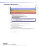
Command/Response Table for SIS Commands (continued) Command Function ASCII Command Response (Host to Unit) (Unit to Host) X@*1B X@*0B X@B VmtX@*1] VmtX@*0] 1*B 0*B Vmt1] Vmt0] Additional description RGB mute commands RGB mute RGB unmute Read RGB mute Global RGB mute Global RGB unmute X#] Mute output X@ RGB (video off). Unmute output X@ RGB (video on). 1 = mute on, 0 = mute off. Mute all RGB outputs. Unmute all RGB outputs.
Command/Response Table for SIS Commands (continued) Command Function ASCII Command Response (Host to Unit) (Unit to Host) Additional description Save, recall, and directly write global presets Save current configuration as a global preset Example: Recall a global preset Example: Directly write a global preset Example: View global preset configuration Response description: Example (MVX 88 VGA): X(, SprX(] 8, Spr08] RprX(] Rpr05] Command character is a comma. Save current ties as preset 8.
Command/Response Table for SIS Commands (continued) Command Function ASCII Command Response (Host to Unit) (Unit to Host) Additional description View ties, gains, mutes, and presets Read RGB (video) output tie Read RGB (video) output tie Read audio output tie View input gain Example: View output mutes Example (MVX 84 VGA): View global preset configuration Response description: Example (MVX 88 VGA): X@& X@% X@$ X$G 3G EVM} X!] X!] X!] X^] -06] X1)1X1)2 ...
Command/Response Table for SIS Commands (continued) Command Function ASCII Command Response (Host to Unit) (Unit to Host) Additional description Front panel lockout (Executive mode) 1X 0X X Exe1] Exe0] Reset global presets Reset one global preset Reset audio input levels EZG} EX(ZG} EZA} Zpg] ZpgX(] Zpa] Reset audio output levels EZV} Zpv] Reset all mutes Reset all RGB delay settings Reset whole switcher EZZ} EZD} EZXXX} Zpz] Zpd] Zpx] Eupload See “Loading Firmware Using an SIS Command” on
Loading Firmware Using an SIS Command NOTE: Firmware can be uploaded two ways: 1. Using the Matrix Switchers Control Program. 2. Using the Eupload SIS command entered via a communications utility such as HyperTerminal. Extron recommends that you upload firmware using the Matrix Switchers Control Program (see “Updating the firmware” on page 49) and reserve this SIS procedure for correcting firmware that has been corrupted and unable to respond to the Matrix Switchers Control Program.
6. Navigate to the folder where you saved the firmware upgrade file. Select the file (see figure 23). NOTE: Ensure that the firmware upgrade is for the MVX Series AV switcher. Valid firmware files must have the file extension “.s19”. Any other file extension is not a firmware upgrade for your switcher. Figure 23. Select the Firmware Upgrade File 7. Click Open. The firmware upload begins.
Matrix Switchers Control Program The Matrix Switchers Control Program communicates with the switcher via the rear panel Remote RS-232 port to provide an easy way to set up ties and sets of ties. The program is compatible with Windows 2000, Windows XP, Windows 7, and newer operating systems. Updates to the program can be downloaded from the Extron website (www.extron.com). Installing the Software The program is contained on the Extron Software Products DVD.
4. Follow the on-screen instructions. By default, the installation of the Matrix Switchers Control Program creates a C:\Program Files\Extron\ Matrix_Switchers directory, and it places the following four icons into a group folder named “Extron Electronics\Matrix Switchers”: • • • • MATRIX Switcher + Control Program MATRIX Switcher + Help Check for Matrix Updates Uninstall MATRIX Switcher Starting the Software 1.
• To create a tie, drag an input box to one or more output boxes. If the Take button is available, click the Take button. • To remove a single tie, drag the output box to its tied input box or to the trash can. To remove a set of ties, drag the input box to the trash can. Figure 28. Matrix Switchers Control Program Window (no Ties) Figure 29.
Updating the Firmware The firmware upgrade utility provides a way to replace the firmware that is coded on the control board of the switcher without taking the switcher out of service. NOTE: Upgrading the firmware does not overwrite the current configuration, presets, or the audio settings. Update the switcher firmware as follows: 1. Visit the Extron website, www.extron.com, click the Download tab, and then click the Firmware link (see figure 30).
NOTE: The version and file size shown are sample values only. 4 4 5 Folder where firmware is installed 6 Figure 31.
7. Connect a computer that runs the Windows operating system to the switcher serial port (see “Installation” for more details). 8. Start the Matrix Switchers Control Program and connect to the matrix switcher. See “Starting the Software,” on page 47. 9. Click Tools > Update firmware. The Extron Firmware Loader appears (see figure 32). 10 Figure 32. Extron Firmware Loader Window 10. Select the MVX matrix switcher and click File > Open. The Choose Firmware File screen appears (see figure 33).
12. In the Firmware Loader window, click Begin (see figure 34). The Total Progress and Progress status bars show the upload progress. The firmware upload may take several minutes. Once the status bars have progressed from 0% to 100%, and Status is listed as Completed, the firmware loader utility resets the switcher. 12 Figure 34. Firmware Loader Screen 13. Click Exit to close the Firmware Loader.
Restore Last-Session’s settings — Loads the icons and icon captions that were saved during the last session. If you saved the changes of the previous session to disk the last time you exited the program, the ties from that session are also loaded. Select Printer ... — Selects the target printer. Print Tie Map — Prints the tie set that is displayed on the screen. Exit — Closes the Extron Matrix Switchers Control Program.
Audio-Output Volume settings — Displays the RGB Delay/Mute/Output-Volume Adjust window (see figure 35 on the preceding page), which displays the output volume level, consumer (-10 dBV) or professional (+4 dBu), for a single output or for all outputs and allows you to change it. This window also displays the RGB delay settings and allows you to change it and allows you to mute and unmute the video and audio output.
Ties as Crosspoints — Displays ties as a grid of inputs and outputs (see figure 38). Current ties are indicated as orange (video and audio), green (video only), or red (audio only) boxes. New ties that will take effect when you click the Take button are indicated by +. Ties that will be broken when you click the Take button are indicated by –. Figure 38. Ties Shown as Crosspoints Icons in I/O Boxes — Erases any numbers in the I/O boxes in either the ties-as-lines window or the ties-as-boxes window.
Using Emulation Mode Emulation mode allows you to set up the software without attaching the switcher to the computer. To use Emulation mode, do the following: 1. Click Start > Programs > Extron Electronics > Matrix Switchers > MATRIX Switcher + Control Pgm. 2. Choose Emulate, and click OK. 3. Choose an emulation file to open, and click OK. The file DEMO.MTX provides a sample of a completed matrix setup. The file NEW.INI provides a blank setup to get you started. 4.
Reference Information This section discusses the specifications, part numbers, and accessories for the MVX Matrix Switchers.
Video output Number/signal type ��������������������� VGA-UXGA RGBHV, RGBS, RGsB, RsGsBs, HDTV, component video (bilevel and tri-level sync), S-video, composite video 44/84 models ��������������������� 4 48/88 models ��������������������� 8 Connectors 44/84 models ��������������������� 4 female 15-pin HD 48/88 models ��������������������� 8 female 15-pin HD Nominal level �������������������������������� 1 Vp-p for Y of component video and S-video, and for composite video 0.
Audio input Number/signal type 44/48 models ��������������������� 84/88 models ��������������������� Connectors 44/48 models ��������������������� 84/88 models ��������������������� Impedance �������������������������������������� Nominal level �������������������������������� 4 stereo, unbalanced 8 stereo, unbalanced 4 female 3.5 mm stereo mini jacks: tip (L), ring (R), sleeve (GND) 8 female 3.
General Power ���������������������������������������������� 100 VAC to 240 VAC, 50-60 Hz, internal, 30 watts Temperature/humidity ���������������� Storage: -40 to +158 °F (-40 to +70 °C) / 10% to 90%, noncondensing Operating: +32 to +122 °F (0 to +50 °C) / 10% to 90%, noncondensing Cooling ������������������������������������������� Convection, vents on sides and top Mounting Rack mount ������������������������ Yes, with included mounting kit Furniture mount ���������������� Yes, with optional under-desk m
Optional Accessories These items can be ordered separately: Remote control, adapters, mounting, controllers, connectors Part Number IR 501 small matrix universal remote control 70-336-01 MBU 149 under-desk mounting kit 70-222-01 3.5 mm mini stereo plug to (2) RCA female adapter 26-592-01 Captive screw to (2) RCA female connector 26-575-01 VGA male to 5 BNC female adapter, 0.5 foot (0.15 m) 26-531-01 VGA male to 5 BNC female adapter, 1.0 foot (0.
Terminated cable assemblies VGA male-to-male cables Part Number VGA M-M MD, 3 feet to 100 feet (0.9 m to 30.4 m) (molded) 26-238-nn VGA M-M BK, 3 feet to 100 feet (0.9 m to 30.4 m) (backshell) 26-238-nn VGAP M-M MD, 3 feet to 25 feet (0.9 m to 7.6 m) (molded) 26-439-nn VGAP M-M BK, 35 feet to 100 feet (10.6 m to 30.4 m) (backshell) 26-439-nn VGA male-to-male with audio cables Part Number VGA-A M-M MD, 3 feet to 50 feet (0.9 m to 15.2 m) (molded) 26-490-nn VGA-A M-M BK, 3 feet to 50 feet (0.
Mounting the Switcher The MVX switchers are housed in a rack-mountable, 1U high, metal enclosures. Included mounting hardware lets you install the switcher in any standard 19-inch rack or into furniture. Tabletop Use For tabletop use, affix one of the supplied self-adhesive rubber feet to each corner of the bottom of the switcher. UL Rack-Mounting Guidelines The following Underwriters Laboratories (UL) requirements pertain to the installation of the matrix switcher into a wall or furniture. 1.
Extron® Warranty Extron Electronics warrants this product against defects in materials and workmanship for a period of three years from the date of purchase.