User’s Guide P/2 DA2 MT Distribution Amplifier 68-435-01 B Printed in the USA 01 02
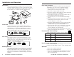
Installation and Operation Easy Setup Procedure Description These easy-to-follow steps describe the general setup of the P/2 DA2 MT. Refer to the previous application diagram. The P/2 DA2 MT Distribution Amplifier can be mounted using the included mounting brackets and screws. Audio input and output connectors and an external DC power supply are also features of the P/2 DA2 MT. See example application diagram below. 1.
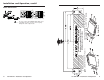
Installation and Operation, cont’d Audio Connections Under Desk P / 2 DA 2 MT ID PIN 11 ID PIN 4 TER I NIPNUPTU T COMPU M O N I TO R COMPU NPUT I N PI U T TER 4 ID PIN 11 ID PIN 2 MT P / 2 DA P/2 DA2 MT • Installation and Operation Thru Desk All dimensions are in inches Thru desk mounting template R D LOCAL P/2 DA2 MT • Installation and Operation BUFFERE 4 (Requires mounting kit P/N 70-077-02) or plugging the audio connectors incorrectly may damage the audio output circuits.
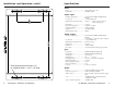
Installation and Operation, cont’d Specifications Video Gain ................................................ (0.7V) unity, (0.8V) 15% Bandwidth ..................................... 300 MHz (-3dB) Video input Number/signal type ................... 1 VGA-UXGA RGBHV, RGBS, RGsB, RsGsBs Connectors ................................... 1 15-pin HD female Minimum/maximum level(s) .... Analog ....... 0.4V to 1.4V p-p with no offset at unity gain Impedance ....................................
CMRR ............................................ >75dB @ 20 Hz to 20 kHz Audio input Number/signal type ................... 1 stereo, unbalanced Connectors ................................... 1 3.5 mm female stereo jack, 2-channel; tip (L), ring (R), sleeve (GND) Impedance .................................... >5 kohms unbalanced, DC coupled Maximum level ............................ +8.5dBu (unbalanced Audio output Number/signal type ................... Connectors ...................................