
User's Manual

P/2 DA2 MT • Installation and OperationP/2 DA2 MT • Installation and Operation
Installation and Operation
3
ID PIN11
ID PIN 4
Easy Setup Procedure
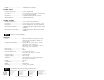
These easy-to-follow steps describe the general setup of the
P/2 DA2 MT. Refer to the previous application diagram.
1. If the P/2 DA2 MT is to be mounted using the mounting
brackets, please refer to the previous section.
2. Power off the computer and its local monitor.
3. Connect the computer’s VGA output to the 15-pin female VGA
input on the front panel of the P/2 DA2 MT.
4. If a local monitor is being used, connect the monitor to the 15-
pin local monitor output on the front panel.
5. Set termination pins (see
Front Panel DIP Switch Settings
below).
6. If audio is being input, connect the audio source to the 3.5 mm
audio input jack on the front panel. Refer to the audio
connector diagrams on the last page.
7. Connect the output display device, such as a projector, VGA-
compatible monitor, etc., to the 15-pin VGA data display
connector on the rear panel of the P/2 DA2 MT.
8. Connect an audio device to the 3.5 mm captive screw audio
output connector on the rear panel. Refer to the audio
connector diagram on the following page.
9. Connect the 9-volt power plug of the included power supply
into the power input jack on the rear panel.
Front Panel DIP Switch Settings
Set the two DIP switch pin positions (on/up or off/down):
Pin 4 Pin 11 Function
off off computer input pins 4 & 11 passed to
local monitor output connector
on on provide ID bit termination when no
local monitor connected
on off provide correct MAC 13” ID bit
termination
Rear Panel DIP Switch Settings
Set the Level/Peaking DIP switch On (up) to increase level and
peaking of the data display, otherwise, set the switch Off (down).
Operation
1. Power on the computer and monitor.
2. Power on the output display device.
3. Power on the P/2 DA2 MT. The LED will light amber when the
power is on and will light green when the power is on and
there is an input present.
2
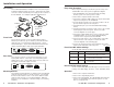
Description
The P/2 DA2 MT Distribution Amplifier can be mounted using the
included mounting brackets and screws. Audio input and output
connectors and an external DC power supply are also features of
the P/2 DA2 MT. See example application diagram below.
Front Panel
The front panel consists of a 2-color LED indicator (amber
indicates power On only, green indicates power On with video
signal present), a 3.5 mm female audio input jack, a 15-pin
female VGA input, a 15-pin female VGA buffered local monitor
output, and 2 DIP switches that set the input termination.
Rear Panel
The rear panel consists of a 9-volt power input jack, a Level/
Peaking DIP switch to control video level and peaking (data
display device only), a 15-pin VGA output connector, and a 3.5
mm captive screw audio output connector.
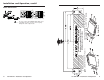
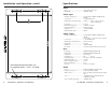
Mounting Bracket
The included mounting brackets are attached to the P/2 DA2 MT
using the 6 bracket screws, as shown on page 5. The unit may
then be mounted under a desk or some other suitable location
using the 4 wood screws (see mounting template). Optional
brackets are also available for vertical mounting (see mounting
template).
BUFFERED
LOCAL MONITOR
COMPUTER
INPUT
ID PIN11
ID PIN 4
P/2 DA2 MT
DATA DISPLAY
POWER
9V DC
0.5A MAX.
LEVEL/PEAKING
SPARE
Stereo
Output
PC Computer
or
Video MonitorProjector
B
U
F
F
E
R
E
D
LOCAL MONITOR
C
O
M
P
U
T
E
R
INPUT
I
D
P
I
N
1
1
ID P
IN
4
P
/
2
D
A
2
M
T
B
U
F
F
E
R
E
D
L
O
C
A
L
M
O
N
I
T
O
R
C
O
M
P
U
T
E
R
I
N
P
U
T
I
D
P
I
N
1
1
I
D
P
I
N
4
P
/
2
D
A
2
M
T
B
U
F
F
E
R
E
D
L
O
C
A
L
M
O
N
I
T
O
R
C
O
M
P
U
T
E
R
I
N
P
U
T
I
D
P
I
N
1
1
I
D
P
I
N
4
P
/
2
D
A
2
M
T
P/2 DA2 MT
PC Audio
Input
With
Mounting
Brackets
Mounted under a Desk
or
Mounted in a Table