
User's Manual

P/2 DA2 MT • Installation and OperationP/2 DA2 MT • Installation and Operation
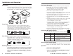
Installation and Operation, cont’d
7
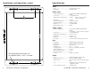
Specifications
Video
Gain ................................................ (0.7V) unity, (0.8V) 15%
Bandwidth ..................................... 300 MHz (-3dB)
Video input
Number/signal type ................... 1 VGA-UXGA RGBHV, RGBS, RGsB,
RsGsBs
Connectors ................................... 1 15-pin HD female
Minimum/maximum level(s) .... Analog ....... 0.4V to 1.4V p-p with no
offset at unity gain
Impedance .................................... 75 ohms
Horizontal frequency .................. 15 kHz to 135 kHz
Vertical frequency ....................... 30 Hz to 170 Hz
Return loss .................................... -38.3dB @ 5 MHz
Maximum DC offset .................... 200mV
Video output
Number/signal type ................... 2 VGA-UXGA RGBHV, RGBS, RGsB,
RsGsBs
(1 for display, 1 for local monitor output)
Connectors ................................... 2 15-pin HD female
Minimum/maximum levels ....... 0.4V to 1.4V p-p
Impedance .................................... 75 ohms
Return loss .................................... -41dB @ 5 MHz
DC offset ....................................... ±5 mV maximum with input at 0 offset
Sync
Input type ..................................... RGBHV, RGBS, RGsB, RsGsBs
Output type .................................. RGBHV, RGBS, RGsB, RsGsBs
Input level ..................................... 3V to 5V p-p
Output level .................................. TTL ............. 5V p-p
Input impedance .......................... 75 ohms or 510 ohms (selectable)
Output impedance ....................... 75 ohms
Max. propagation delay .............. 18.8 nS
Max. rise/fall time ....................... 4 nS
Polarity .......................................... Positive or negative
Audio
Gain ................................................ Unbalanced 0dB, balanced +6dB
Frequency response .................... 20 Hz to 20 kHz, ±0.05dB
THD + Noise ................................. 0.03% @ 1 kHz at rated maximum output
drive
S/N ................................................ >90dB, balanced, at rated maximum
output drive (21dB)
Stereo channel separation .......... >80dB @ 1 kHz
6
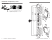
Recommended pilot drill hole size
for supplied screws = 3/32” x 1/4” deep.