
User's Manual


P/2 DA1 Operation and SpecificationsP/2 DA1 Installation and Operation
Installation
32
The Extron P/2 DA1 is a one input, one output VGA line driver. It
boosts the video signal between a laptop or desktop computer (input
device) and a monitor or large screen projector (output device).
Features
• The P/2 DA1 accepts and outputs VGA, XGA, SXGA, RsGsBs,
RGsB, RGBS, and RGBHV signals.
• The gain/peaking switch increases video signal voltages to
compensate for signal degradation caused by long cables.
Installation
To install the P/2 DA1, do the following:
1. Turn off power to the input and output devices and unplug
their power cords.
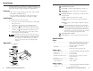
2. Connect the computer to the 15-pin HD male input
connector (see
1
in the “Operation” illustration below).
3. Connect the output device to the 15-pin HD female output
connector (see
5
in the “Operation” illustration below).
4. Reattach power cords, and apply power to the P/2 DA1
and to the input and output devices.
Many laptop computers have an external video port, but
they require special commands to output the video to that
connector. Also, many laptops’ screens shut off after the
port is activated. See the computer’s user’s guide for
details, or contact Extron for a list of laptop keyboard
commands.
Operation
1
15-pin HD input connector
2
Power LED — Lights to indicate that the P/2 DA1 is on.
3
Signal LED — Lights to indicate that an input signal is
being received.
4
Gain/peaking switch — Compensates for cable resistance
and capacitance.
Normal — Output is the same level as input.
Medium — 50% of the total gain is applied. Peaking is
applied.
Maximum — 100% of the total gain is applied. Peaking is
applied.
If the signal cable between the P/2 DA1 and the output
device is shorter than approximately 125 feet, and the gain
switch is set to Medium or Maximum, the image may be
overcompensated. If the edges of the image seem to exceed
their boundaries, or if thin lines and sharp edges look thick
and fuzzy, try changing the gain/peaking setting.
5
15-pin HD output connector
6
Power supply — 110–250 V desktop for international use.
Specifications
Video
Gain ................................................... 0 dB, 0.6 dB, 1.2 dB, selectable: when input is
0.7 Vp-p, output is 0.7 V, 0.75 V, 0.8 Vp-p
when switch is at normal, medium, and
maximum positions, respectively
Bandwidth ........................................ 300 MHz (-3 dB)
Note: ID bits will be passed through.
Video input
Number/signal type ...................... 1 VGA-UXGA RGBHV, RGBS, RGsB, RsGsBs
Connectors ....................................... (1) 15-pin male
Nominal level .................................. 0.7 Vp-p for RGB
Minimum/maximum levels ......... Analog: 0.3 VDC to 1.5 VDC p-p with no
offset at unity gain
Impedance ........................................ 75 ohms
Horizontal frequency ..................... 15 kHz to 135 kHz
Vertical frequency ........................... 30 Hz to 170 Hz
Video output
Number/signal type ...................... 1 VGA-UXGA RGBHV, RGBS, RGsB, RsGsBs
Connectors ....................................... (1) 15-pin HD female
VGA IN
POWER
POWER
NORMAL
GAIN/PEAKING
MEDIUM
MAXIMUM
VGA OUT
SIGNAL
SIGNAL
1
2
3
4
5
To computer
To display device
6