User’s Manual RGB 190F RGB 192 RGB 198 Analog Computer-Video Interface www.extron.com Extron Electronics, USA Extron Electronics, Europe Extron Electronics, Asia Extron Electronics, Japan 1230 South Lewis Street Anaheim, CA 92805 USA 714.491.1500 Fax 714.491.1517 Beeldschermweg 6C 3821 AH Amersfoort The Netherlands +31.33.453.4040 Fax +31.33.453.4050 135 Joo Seng Road, #04-01 PM Industrial Building Singapore 368363 +65.6383.4400 Fax +65.6383.
Precautions Safety Instructions • English This symbol is intended to alert the user of important operating and maintenance (servicing) instructions in the literature provided with the equipment. This symbol is intended to alert the user of the presence of uninsulated dangerous voltage within the product's enclosure that may present a risk of electric shock. Caution Read Instructions • Read and understand all safety and operating instructions before using the equipment.
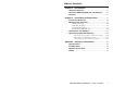
Table of Contents Chapter 1 • Introduction .......................................................... 1-1 About this Manual ................................................................ 1-2 About the RGB 190F, RGB 192 and RGB 198 ............. 1-2 Features ...................................................................................... 1-3 Chapter 2 • Installation and Operation ......................... 2-1 Installation Overview ..........................................................
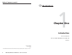
Table of Contents, cont’d RGB 190F, RGB 192 1 Chapter One Introduction About this Manual About the RGB 190F, RGB 192 and RGB 198 Features 68-647-01 Rev. C Printed in USA 10 04 All trademarks mentioned in this manual are the properties of their respective owners.
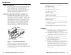
Introduction, cont’d Introduction Each RGB interface has two or more model options: About this Manual This manual contains information about the Extron RGB 190F, RGB 192 and RGB 198 universal interfaces, detailing how to operate and configure them. The three interfaces are functionally identical, with the exception of the RGB 192 and RGB 198’s audio capabilities and the RGB 198’s extended enclosure. All interfaces are described in this manual; differences are noted where they exist.
Introduction, cont’d RGBHV, RGBS, or RGsB outputs — Select the output format via cabling setup and front panel DIP switch. Serration pulse switch — This DIP switch-selectable feature adds or strips the serration pulses from the output signal to make it compatible with digital display devices. Use the serration pulse switch if flagging or bending occurs at the top of the video display.
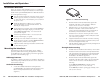
Installation and Operation, cont’d Installation and Operation Installation Overview This is an overview of the installation process. You will find detailed installation and operation instructions in this chapter. AU Install and set up the RGB 190F, RGB 192 or RGB 198 interfaces by following these basic steps: 1 Turn off all of the equipment (computers, remote controls, interface, projector/monitor, local monitor and speakers or other audio device). Disconnect the power cords from the power source.
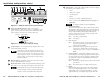
Installation and Operation, cont’d 6" Deep Rack Shelf 1/4 Rack Width Front False Faceplate Front false faceplate uses 2 screws. DIO AU CO MP UT ER MO NI TO RG R H- SH IF T B 19 R SERSOGE L V LE 2 1 ON 2 3 4 5 6 P N. IO DDS MO NO AUD M. AU DIO CO MP INP UT UT ER MO NIT OU OR UN H-S TP UT IVE HIF RG RS AL T SERR L ESOG VE L B INT 19 ER 8 FAC E ON 1 2 3 DDSP NO M. MON AUDI . O 4 5 6 125 V 50/6 0 Hz 5A 125 V 50/6 0 Hz Use 2 mounting holes.
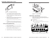
Installation and Operation, cont’d 1 2 3 4 COMPUTER M O N I TO R INPUT OUTPUT 6 5 6 11 10 RGB 198 DIP switches — This bank of DIP switches is used to configure the interface. The switches control: • Level • SOG (sync on green) • Serration pulses • DDSP • Monitor or no monitor (ID bit termination) • Mono or stereo audio (RGB 192 and 198 only, spare on RGB 190F) UNIVERSAL INTERFACE AUDIO H-SHIFT SERR SOG LEVEL DDSP NO MON. M .
Installation and Operation, cont’d options, such as serration pulse and video termination changes, have been tried. To verify the polarity before connection, check the no-load power supply output with a voltmeter. On — The interface uses DDSP, which does not process the sync signal. Alternatively, an Extron P/S 100 Universal 12VDC Power Supply can power up to six RGB 190F or RGB 192 interfaces using only one AC power connector. DDSP disables the horizontal and vertical centering controls.
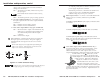
Installation and Operation, cont’d CAUTION Wiring the audio incorrectly can damage the audio output circuits. Connect the sleeve(s) to ground (GND). Connecting the sleeve(s) to a negative (-) terminal will damage audio output circuits. R R Unbalanced Output Tip Ring Sleeve (s) Tip Ring L/ Mono L/ Mono Tip See caution Sleeve Tip See caution 5. To test the system setup and output, substitute a video test generator for the computer input.
Installation and Operation, cont’d RGB 190F, RGB 192 A Appendix A Reference Information Specifications Included Parts Optional Accessories Cables 2-12 RGB 190F, RGB 192 and RGB 198 • Installation and Operation
Reference Information, cont’d Reference Information Specifications Video Gain ............................................... Unity (0.7 V), (0.8 V) 15% with 3 dB peaking Bandwidth .................................... 300 MHz (-3 dB) Max. rise/fall time ....................... 1.5 ns Video input and loop-through Number/signal type ................... 1 analog VGA–UXGA, Mac, Sun RGBHV, RGBS, RGsB 1 buffered local monitor loop-through identical to the input Connectors ....................................
Reference Information, cont’d External power supply (RGB 190F, RGB 192) 100 VAC to 240 VAC, 50/60 Hz, external, autoswitchable; to 12 VDC, 1 A, regulated, included Power input requirements (RGB 190F, RGB 192) 12 VDC, 0.35 A Temperature/humidity .............. Storage -40° to +158°F (-40° to +70°C) / 10% to 90%, noncondensing Operating +32° to +122°F (0° to +50°C) / 10% to 90%, noncondensing Rack mount RGB 198, RGB 198EU ......
Reference Information, cont’d Cables Included items Part number Rubber feet IEC power cord Tweeker BNC cable Part number BNC-5 3’ HR 26-260-15 BNC-5 6’ HR 26-260-01 BNC-5 12’ HR 26-260-02 Universal 12VDC external power supply (RGB 190 and RGB 192 only) 70-055-01 BNC-5 25’ HR 26-260-03 Under-desk mounting kit instruction card 68-461-01 BNC-5 50’ HR 26-260-04 3.
Reference Information, cont’d A-8 RGB 190F, RGB 192 and RGB 198 • Reference Information