RGB 320 Switching Interface Six Input, Two Output System 68-341-01 Printed in the USA
Precautions Safety Instructions • English This symbol is intended to alert the user of important operating and maintenance (servicing) instructions in the literature provided with the equipment. This symbol is intended to alert the user of the presence of uninsulated dangerous voltage within the product's enclosure that may present a risk of electric shock. Warning Power sources • This equipment should be operated only from the power source indicated on the product.
Contents Contents Legend of Icons ................................................................................................................. ii Revision Information .......................................................................................................... ii Chapter One • Introduction to Switching Interface What is a Switching Interface? .................................................................................................... 1-1 Function .................................
Contents Figure 3-3. RGB 322/324/326/340 Differences ............................................................................................ Figure 3-4. RGB 320 Front Panel A/V Mode and Input Selection Buttons ................................................... Figure 3-5. Select the A/V Mode by Pressing the Button on the RGB 320 Front Panel .............................. Figure 3-6. Select the Desired Input by Pressing Its Button ........................................................................
Contents RGB 320 Switching Interface System User’s Manual 1 Chapter One Introduction to Switching Interface What is a Switching Interface? Extron • User’s Manual • RGB 320 Switching Interface System Features Specifications
Chapter 1 • Introduction to the RGB 320 Switching Interface System What is a Switching Interface? Extron’s RGB 320 combines an interface and a switcher with six inputs and two outputs. It was designed as a system solution for installation environments such as conference or training rooms and command/control centers. The six inputs can use RGsB, RsGsBs, RGBS, RGBHV and line level audio. There are two buffered outputs.
Chapter 1 • Introduction to the RGB 320 Switching Interface System • • • • horizontal shift (from RGB 322, RGB 324 & RGB 340) vertical shift (from RGB 324 & RGB 340) video level (from RGB 324 & RGB 340) audio level (from RGB 324 & RGB 340) The RGB 320 saves these adjustments in a memory associated with each input. The RGB 320 has 15 memory blocks for each of the six inputs. The memory blocks store the picture controls needed for an application or installation.
Chapter 1 • Introduction to the RGB 320 Switching Interface System Features • High bandwidth – The RGB 320 provides a 220 MHz bandwidth for effective transmission of high resolution computer video and audio signals. • Central control– The RGB 320 interfaces and switches input sources from buffers throughout the room to two displays for professional presentations. • RS-232 control – Allows for third party control system (such as AMX® or Crestron®) integration via the RS-232 serial port.
Chapter 1 • Introduction to the RGB 320 Switching Interface System Sync (continued) Audio input Max. propagation delay _ Max.
Chapter 1 • Introduction to the RGB 320 Switching Interface System RGB 322, RGB 324, RGB 326 and RGB 340 Input Buffers The RGB 322, 324 and 326 are each mounted on a two-gang wall plate that can be installed in a wall, conference table, podium, etc., while the RGB 340 mounts under a table or shelf. Each buffer has a 9-pin input connector compatible with computers that output analog RGsB, RsGsBs, RGBS and RGBHV. ________ These buffer units have their own User’s Manual (68-338-01).
Chapter 1 • Introduction to the RGB 320 Switching Interface System RGB 320 Switching Interface System User’s Manual 2 Chapter Two Rear Panel Connections Connecting the RGB 320 Switching Interface Rear Panel Connectors Choosing Cables Composite Cables Buffer Input Cables Extron • User’s Manual • RGB 320 Switching Interface System
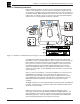
Installing RGB 320 Switching Interface Components • Chapter 2 Connecting the RGB 320 Switching Interface The RGB 320 has six inputs and two outputs, plus connections for RS-232 controls. Figure 2-1 shows an example of the types of equipment that may be part of the interface system. Each RGB 320 input has five BNC connectors to allow for RGsB, RGBS or RGBHV input. There are also connectors for stereo audio.
Chapter 2 • Installing the RGB 320 Switching Interface Components Rear Panel Connectors Each of the six inputs has the following connectors: • 5 BNCs Red video (R) Green video (G) Blue video (B) Horizontal sync, or composite (H/HV) Vertical sync (V) • 3.5 mm 10-pole captive screw (left 5 for audio) Left channel audio + Left channel audio – Ground (common to both left and right channels) Right channel audio + Right channel audio – • 3.
Installing RGB 320 Switching Interface Components • Chapter 2 Audio Input Connections The 10-pole receptacles are located on the rear panel below the BNC connectors. Inputs are on the left side, and outputs are on the right. Each input receptacle has five poles on its left labeled for left (L) and right (R) stereo, and the input number is also labeled. Polarity (+/-) and ground are marked below. The right five poles are labeled COM and PWR for use with an RGB 322/324/326/340 input buffer.
Chapter 2 • Installing the RGB 320 Switching Interface Components Choosing Cables for Remote Inputs With the RGB 320 as the center of a computer video interface system, the input connectors have specific functions, and the connectors must not be misused. The ideal installation will use the RGB 322, RGB 324, RGB 326 or RGB 340 as inputs through an installation (or composite) cable. Most of the examples used in this manual will make this assumption.
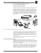
Installing RGB 320 Switching Interface Components • Chapter 2 Buffer Input Cables Computer video signals coming through a buffer unit (RGB 322/324/326/340) use the red, green, blue, horizontal and vertical sync connectors. The audio, communications and power (to the buffer) come through the 3.5 mm, 10-pole connectors below the BNC connector. Red White Green Blue Black Yellow Grn/Blk White Black Shields Red Black Black Orange Brown Violet Gray Figure 2-9a.
Chapter 2 • Installing the RGB 320 Switching Interface Components RGB 320 Switching Interface System User’s Manual 3 Chapter Three Operating the RGB 320 Panels Controlling the RGB 320 Interface Input Buffer Control (RGB 322/324/326/340) Using the RGB 320 Front Panel Buttons Making Adjustments from the RGB 320 Front Panel Rear Panel Switches Extron • User’s Manual • RGB 320 Switching Interface System
Operating the RGB 320 Panels • Chapter 3 Controlling the RGB 320 Interface The RGB 320 can be controlled from the front panel, from an input buffer, from an external RS-232 device or from Extron’s Windows® based control software. This includes selecting video, audio or both from one of six inputs, adjusting horizontal and vertical centering or adjusting the video and audio levels. See Chapter 4 for Windows® software and Appendix A for RS-232 programming. Figure 3-1.
Chapter 3 • Operating the RGB 320 Panels Front Panel Controls There are panel controls for adjusting four functions for the selected input. These will be explained later in this chapter. Although the knobs can be turned endlessly (no physical limit), the adjustment level will stop at its highest or lowest value. Input buffer control (RGB 322/324/326/340) Before going into the operation of the RGB 320 panel, here is an overview of the input buffers that can be used with the RGB 320.
Operating the RGB 320 Panels • Chapter 3 Using the RGB 320 Front Panel Buttons Of the seven buttons on the front panel shown in Figure 3-4, the left-most button (A/V Mode) determines what will be selected (audio, video or both), and the other six buttons are used to select an input. Figure 3-4. RGB 320 Front Panel A/V Mode and Input Selection Buttons The A/V Mode button has two LEDs next to it. The top one (red) is for video and the bottom one (green) is for audio.
Chapter 3 • Operating the RGB 320 Panels Making Input Adjustments from the RGB 320 Front Panel When adjustments are being made from the front panel, an input buffer or an RS-232 device, the results are displayed on the LCD screen. Otherwise, the default screen displays the horizontal and vertical frequencies. See Figure 3-7. ________ Do not make adjustments immediately after switching inputs.
Operating the RGB 320 Panels • Chapter 3 Diagnostic LEDs The front panel has six diagnostic LEDs. The right-most pair monitor +15 and -15 voltages, and the middle pair monitors +8 and -8 voltages. If any of these four LEDs are not lit, the system will malfunction. The left-most pair of LEDs will blink during RS-232 communication with a controlling device. Tx is transmit and Rx is receive. ________ Tx blinks each time a panel change has been completed to notify the host of a change in status. Figure 3-10.
Chapter 3 • Operating the RGB 320 Panels RGB 320 Switching Interface System User’s Manual 4 Chapter Four Using Windows® Control Program Installing Windows® Software Control Normal Windows Control Panel Executive Mode Panel Extron • User’s Manual • RGB 320 Switching Interface System RGB 320 Help
Using Windows® Control Software Installing Windows® Control Software This chapter is dedicated to using Extron’s “Windows Control Program for RGB 320 via RS-232” software. Extron supplies this software that runs in the Windows® operating system, version 3.1 or later. Communication between the computer software and the RGB 320 is established after connecting the computer to the RS-232 port on the rear panel of the RGB 320. 1. Connect the PC’s serial port to the RS-232 connector on the back of the RGB 320.
Using Windows® Control Software Normal Windows Control Panel Figure 4-3 shows an example of the normal Windows control panel. In addition to the six input switches, there are: ○ ○ ○ ○ ○ ○ ○ ○ ○ ○ ○ ○ ○ ○ ○ ○ ○ ○ ○ ○ ○ ○ ○ ○ ○ ○ ○ • The four controls have the same functions as the four knobs on the front panel. The up/down nudge buttons change the value of the function, while the numeric value is displayed in the window next to the set of buttons. Figure 4-3.
Using Windows® Control Software RGB 320 Help Double-click on the Help icon (or press F1 at any time) to open the Help window. Below is an example of what this might look like. As with all Windows® help files, clicking on the underlined words will give more detailed help. Extron’s RGB 320 Control Program Help Contents To learn how to use Help, press F1 or choose Using Help from the Help menu.
Using Windows® Control Software RGB 320 Switching Interface System User’s Manual A Appendix A Programming the RGB 320 Remote Control Port (RS-232 and Contact Closure) Host-to-RGB 320 Instructions Command/Response Table RGB 320-Initiated Messages Extron • User’s Manual • RGB 320 Switching Interface System
RS-232 Programming • Appendix A Remote Control Port (RS-232 and Contact Closure) Figure A-1 shows the RS-232 port connector. This is used to connect to a host, or to an external controlling device, such as a computer or control panel, that can generate the proper command codes and can recognize the RGB 320 responses. In addition to having RS-232 connections (pins 2, 3 and 5), there are also six contact closure inputs that share the ground on pin #5.
Appendix A • RS-232 Programming Command/Response Table Definitions and abbreviations: ¿ = CR/LF = input #1 through 6, or 0 = input disconnected = 0 thru 255 (enhancement control range) = xxx.xx (frequency in Hz or kHz) = 0 thru 9 (10 steps of audio gain) = numeric value -15 thru +09 = controller software version to 2nd decimal place = 0 or 1, 0 = Off, 1 = On = 15 thru 1 (15 steps of audio attenuation) · = space (If indicated, the space must be there.
RS-232 Programming • Appendix A RGB 320-Initiated Messages When a local event takes place, such as a front panel operation, the RGB 320 responds by sending a message to the host. These RGB 320-initiated messages are listed below. (C) COPYRIGHT 1997, EXTRON ELECTRONICS RGB 320, VX.XX ¿ Power-on message: The AC power has been applied. (x.xx is the software version number.
Appendix A • RS-232 Programming RGB 320 Switching Interface System User’s Manual B Appendix B Reference Material Related Product Lists Glossary of Terms Extron • User’s Manual • RGB 320 Switching Interface System
Reference and Glossary • Appendix B Related Parts Monitor Breakout Cables MBC VGA/XGA HR MBC Mac/Quadra MBC SUN Sparc HR 26-162-01 26-018-02 26-424-01 Laptop Breakout Cables LBC VGA HR 3’ LBC VGA HR 6’ LBC VGA HR 12’ LBC Mac HR 3’ LBC Mac HR 6’ LBC Mac HR 12’ LBC SUN HR 3’ (61 kHz) LBC SUN HR 6’ (61 kHz) LBC SUN HR 12’ (61 kHz) LBC SUN HR 3’ (71 kHz) LBC SUN HR 6’ (71 kHz) LBC SUN HR 12’ (71 kHz) LBC SUN HR 3’ (81 kHz) LBC SUN HR 6’ (81 kHz) LBC SUN HR 12’ (81 kHz) LBC Mac/VGA 35 HR 26-224-02 26-224-01
Appendix B • Reference and Glossary Glossary of Terms For a complete glossary, see Extron’s web site (http://www.extron.com) AC – Alternating current. The flow of electrons that changes direction alternately. AC reset – The status that changes when power is removed from a device. Many electronic devices have live power inside, even after “power off” has been initiated from a panel or remote control device. This is not the same as “AC reset”, when power is removed at the AC cord. Amp – Ampere.
Reference and Glossary • Appendix B Cable equalization – The method of altering the frequency response of a video amplifier to compensate for high frequency losses in cables that it feeds. See peaking. Capacitance – The storing of an electrical charge. Capacitance is a condition that exists between conductors in a cable. At high frequencies, this represents an impedance called capacitive reactance (Xc), which can cause signal loss or distortion.
Appendix B • Reference and Glossary Distribution amplifier – DA. A device that allows connection of one input source to multiple, isolated (buffered) output sources such as monitors or projectors. FCC – Federal Communications Commission. The US governmental agency that controls and makes all policy for the use of broadcast airwaves. Field – One half of a standard television frame, containing every other line of information.
Reference and Glossary • Appendix B Luminance – The photometric radiance of a light source. The signal that represents brightness in a video picture. Luminance is any value between black and white. Luminance is abbreviated as Y. Also see chrominance. MHz – Megahertz. One million cycles per second. NTSC – National Television Standards Committee. The television standard, for North America and parts of South America, having 525 lines/60 Hz (60 Hz refresh). Two fields per frame and 30 frames per second.
Appendix B • Reference and Glossary RS-232 – An Electronic Industries Association (EIA) serial digital interface standard specifying the characteristics of the communication path between two devices using D-type connectors. This standard is used for relatively short range communications and does not specify balanced control lines. A serial control standard with a set the number of conductors, data rate, word length and type of connector to be used.
Reference and Glossary • Appendix B Index E A H Adjustments from front panel 3-4 warning (making too soon) 3-4 Attenuation audio/video level 1-3 RS-232 programming A-2 defined B-2 Audio follow feature 1-3 front panel indicators 3-3 defined B-2 Audio level features 1-2, 1-5 from RS-232 control A-2 operation from buffer 3-1 operation from RGB 320 3-4 operation from software 4-2 H.
FCC Class A Notice Note: This equipment has been tested and found to comply with the limits for a Class A digital device, pursuant to part 15 of the FCC Rules. These limits are designed to provide reasonable protection against harmful interference when the equipment is operated in a commercial environment. This equipment generates, uses and can radiate radio frequency energy and, if not installed and used in accordance with the instruction manual, may cause harmful interference to radio communications.
EXTRON ELECTRONICS/RGB SYSTEMS, INC. 1230 South Lewis Street, Anaheim, CA 92805 800.633.9876 714.491.1500 FAX 714.491.1517 U.S.A. EXTRON ELECTRONICS, EUROPE Beeldschermweg 6C, 3821 AH Amersfoort +31.33.453.4040 FAX +31.33.453.4050 The Netherlands EXTRON ELECTRONICS, ASIA 41B Kreta Ayer Road, Singapore 089003 +65.226.0015 FAX +65.226.0019 Singapore EXTRON ELECTRONIC INFORMATION EXTRONWEB™: www.extron.com EXTRONFAX™: 714.491.