User’s Manual RGB 400 Series Mountable Interfaces EXTRON ELECTRONICS/RGB SYSTEMS, INC. 1230 South Lewis Street, Anaheim, CA 92805 800.633.9876 714.491.1500 FAX 714.491.1517 USA EXTRON ELECTRONICS, EUROPE Beeldschermweg 6C, 3821 AH Amersfoort +31.33.453.4040 FAX +31.33.453.4050 The Netherlands EXTRON ELECTRONICS, ASIA 41B Kreta Ayer Road, Singapore 089003 +65.226.0015 FAX +65.226.0019 Singapore EXTRON ELECTRONIC INFORMATION EXTRONWEB™: www.extron.com EXTRONFAX™: 714.491.
Precautions Safety Instructions • English This symbol is intended to alert the user of important operating and maintenance (servicing) instructions in the literature provided with the equipment. This symbol is intended to alert the user of the presence of uninsulated dangerous voltage within the product's enclosure that may present a risk of electric shock. Caution Read Instructions • Read and understand all safety and operating instructions before using the equipment.
Table of Contents Chapter 1 • Introduction .......................................................... 1-1 About this Manual ................................................................ 1-2 About the RGB 400 Series Interfaces .......................... 1-2 Features ...................................................................................... 1-2 RGB 400 Series features ......................................................... 1-2 Additional RGB 402 and RGB 404 features ..........................
Table of Contents, cont’d Appendix C • Dimensions ........................................................ C-1 RGB RGB RGB RGB RGB RGB 400 402 404 406 408 408 Panel Panel Panel Panel Panel Panel Dimensions ............................................... C-2 Dimensions ............................................... C-3 Dimensions ............................................... C-4 Dimensions ............................................... C-5 Dimensions ...............................................
Introduction, cont’d Introduction About This Manual This manual contains information about the RGB 400 Series interfaces and on how to operate and configure them. RGB 400 Series About The RGB 400 Series Interfaces The RGB 400 Series are 300 MHz (-3dB) bandwidth, analog computer-video interfaces that can be mounted in walls or furniture. The RGB 400 and RGB 406 are two-gang wall plate size, the RGB 402 and RGB 404 are three-gang size, and the RGB 408 is four-gang size.
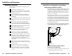
Installation and Operation, cont’d Installation and Operation Installation Overview To install and set up an RGB 400 Series interface, follow these basic steps: 2-2 1 Determine the installation location. 2 Prepare the site for installation. Use the supplied template to mark the rough-in cutout, then cut out the wallboard or wood. 3 Set the DIP (dual in-line package) switches and jumpers. These items will be inaccessible after installation.
Installation and Operation, cont’d Preparing the installation site and installing the wall box Actual-size rough-in templates for each model are provided in Appendix B. If needed, make a 100% size photocopy of the appropriate template to use for installation. Compare the photocopy with the faceplate and wall box to make sure the photocopy size is the same as the equipment.
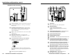
Installation and Operation, cont’d RGB 406 front and rear features Front and rear panel (circuit board) features 14 RGB 400 front and rear features 12 J11 J12 J9 J11 HIGH Z J12 INPUT 75 Ohm J8 J10 ON INPUT 1 2 SW1 J9 HIGH Z 1 2 SW1 AUTO POWER J8 J10 AUDIO J13 ON 75 Ohm H. SHIFT AUTO POWER 1 = +5V 20 mA max. 2 = –5V 20 mA max. 3 = Ground J13 RGB 406 SW1 H. SHIFT 1 = +5V 20 mA max. 2 = –5V 20 mA max.
Installation and Operation, cont’d RGB 402 front and rear features 13 14 14 Yellow 13 16 15 Red Black Green S-VIDEO VIDEO J9 AUDIO HIGH Z INPUT J8 J10 75 Ohm L R AUTO POWER NETWORK H. SHIFT 1 = +5V 20 mA max. 2 = –5V 20 mA max. 3 = Ground Extron 3 4 5 6 FRONT 1 Auto power LED — If active sync pulses are present, power and this LED turn on. If not, power and this LED turn off. 2 H. Shift (horizontal shift) control — This controls the horizontal centering.
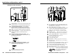
Installation and Operation, cont’d RGB 404 front and rear features 18 18 Yellow 17 16 19 Red Black Green J12 VIDEO S-VIDEO L R J11 17 J9 HIGH Z 2 CH1L 3 4 5 CH1R 6 7 8 9 10 NETWORK CH1R PC SW1 1 2 1 AUTO POWER A U D I O 33-323-01 L 3.5 mm Signal RCA REV. A 79-08 R Ground Ground CH1L & CH1R outputs are CH2L & CH2R outputs are generated from RCA inputs. generated from 3.5 mm inputs. 75 Ohm J8 J10 ON INPUT J13 H. SHIFT 1 = +5V 20 mA max. 2 = –5V 20 mA max.
Installation and Operation, cont’d RGB 408 front and rear features 15 J11 J12 J9 HIGH Z INPUT 1 2 SW1 J8 J10 ON 75 Ohm AUTO POWER AUDIO J13 H. SHIFT 1 = +5V 20 mA max. 2 = –5V 20 mA max. 3 = Ground Extron RGB 408 ON SW1 FRONT 1 2 3 4 5 6 1 Auto power LED — If this LED is on, power and video sync pulses are present. If no sync is present, power and this LED turn off. 2 H. Shift (horizontal shift) control — This controls horizontal centering.
Installation and Operation, cont’d Setting DIP switches and jumpers DIP switches and jumpers must be set and tested before the interface is secured into the wall box, wall or furniture. DIP switches ON 1 2 DIP switch module SW1 contains two DIP switches (SW1-1 and SW1-2). The module is located on the circuit board on the back of the interface, as shown on pages 2-6, SW1 2-7, 2-9, 2-11 and 2-13. In these illustrations, the On position is to the left.
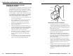
Installation and Operation, cont’d Cabling RCA connectors Adapter Plate INP U AU TO T HIG HZ PO WER 75 H. SH IFT For composite video, solder the center conductor of a coaxial cable to the central solder cup of the RCA connector. Solder the cable’s shield to the grounded grounding tab. See the leftmost and center illustrations below.
Installation and Operation, cont’d If shielded twisted-pair wires are used for audio output for the RGB 404, RGB 406 or RGB 408, the shields should be connected to either pin 3 (RGB 406/408) or pins 3 and 8 (RGB 404) of the audio output captive screw connector. Twist the wires from the braided shield together to form a multi-strand wire, then insert it into the receptacle side of the captive screw connector. See the “Wiring audio output captive screw connectors” illustration on the next page.
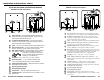
Installation and Operation, cont’d output captive screw connector. See “Connecting shields” earlier in this chapter for details. Connecting audio cables — RGB 406, RGB 408 Using installation cable Extron’s Install Plenum bulk cable (shown here) is ideal for mountable interfaces such as the RGB 400 Series models. Six Mini, High-resolution Coaxial Conductors Each RGB 406 or RGB 408 accepts an unbalanced audio input from a front panel 3.
Installation and Operation, cont’d 3. Check the cabling and the audio connector wiring, and make adjustments as needed. 4. Verify that the High Z/75 Ohm video input termination toggle switch on the front panel has been set correctly. 5. For digital display devices (including LCD, DLP and plasma devices), try turning DDSP on or off using the rear panel SW1-2 DIP switch. 6. Call Extron’s customer support hotline if needed.
Installation and Operation, cont’d 4. For all models, carefully place the interface through the opening in the wall or furniture and into the wall box (if one is used). Take care not to damage the cables. 5. Mount the interface faceplate to the wall box with the provided machine screws (as shown below), or attach the interface directly to the furniture with wood or metal screws.
Installation and Operation, cont’d RGB 400 Series A Appendix A Specifications Specifications 2-26 RGB 400 Series Installation and Operation
Specifications, cont’d Specifications These specifications apply to all models unless otherwise noted. Video input Number/type .............................. 1 analog RGBHV, RGBS, RGsB Connectors .................................... 1 9-pin male D connector for MBC/LBC cable or buffer Nominal level(s) .......................... Analog — 0.3V to 1.45V p-p Impedance .................................... 75 ohms or HI Z, switchable (set to 75 ohms if no local monitor is connected) Horizontal frequency ........
Specifications, cont’d Audio output — RGB 404 (channels 1 and 2) Number/type .............................. 2 buffered, stereo (2 channel), balanced/unbalanced Connectors .................................... 3.5 mm captive screw terminal, 5 conductor Impedance .................................... 50 ohms unbalanced, 100 ohms balanced Gain error ..................................... ±0.1dB channel to channel Drive (600 ohm) ...........................
Specifications, cont’d RGB 400 Series B Appendix B Templates RGB 400 and RGB 406 Cut-out Template RGB 402 and RGB 404 Cut-out Template RGB 408 Cut-out Template A-6 RGB 400 Series Specifications
Templates, cont’d Templates All the templates in this section are actual size. Also, they all include the recommended 0.1” (0.25 cm) clearance on all sides of the electrical wall box to allow room for the raised areas surrounding the knockouts. RGB 402 and RGB 404 Cut-out Template Use this template for cutting a hole in a wall or furniture for the 3-gang size electrical box for an RGB 402 or RGB 404. The dashed line in each template indicates the cut-out area for installing a wall box.
B-4 RGB 400 Series Templates The dashed line indicates the cut-out area (3.95"H x 7.58"W) for installing the electrical wall box. Use this template for cutting a hole in a wall or furniture for the electrical box and pass-through connections for the 4-gang size RGB 408. RGB 408 Cut-out Template To install the interface without a wall box, use the cut-out area (3.00"H) indicated by the dotted line. The light gray area represents the layout of the electrical box (3.75"H x 7.
C-2 RGB 400 Series Dimensions DETAIL A H. SHIFT Extron B 75 Ohm HIGH Z B RGB 400 Series Dimensions L AUDIO C RGB 402 R S-VIDEO HAND SAND TO 0.06" RADIUS AROUND TOP EDGES. C VIDEO C STANDOFFS: 75 Ohm HIGH Z DETAIL C (VIEWED FROM BACK SIDE) DETAIL C DETAIL B SCALE: 2/1 DETAIL A ø.120 THRU, WITH ø.250 C'BORE ON BOTH SIDES, .040 DEPTH ON THE NEAR SIDE, AND .020 DEPTH ON THE FAR SIDE. (2 PLCS.) DETAIL A ø.156 THRU WITH C'SINK ø.
C-4 RGB 400 Series Dimensions ø.125 THRU ø.230 THRU DETAIL A H. SHIFT ø.230 THRU ø.125 THRU DETAIL A E B ø.213 A U D I O H. SHIFT AUTO POWER PC L AUDIO E E C VIDEO R 75 Ohm HIGH Z RGB 404 NETWORK C S- VIDEO 2 REQ'D ø.085 THRU (2 PLACES) ø.156 THRU C'SINK ø.290 x 82˚ (4 PLACES) STANDOFFS: 2 REQ'D (VIEWED FROM BACK SIDE) RGB 400 Series Dimensions ø.156 THRU WITH C'SINK ø.
.225 .190 DETAIL B ø.201 DETAIL A RGB 400 Series Dimensions DETAIL C H. SHIFT AUTO POWER Extron .449 4– R .132 0.000 .06 ø.120 THRU, WITH ø.250 C'BORE ON BOTH SIDES, .040 DEPTH ON THE NEAR SIDE, AND .020 DEPTH ON THE FAR SIDE. (2 PLCS.) .403 0.000 0.609 ø 0.230 THRU 1.395 1.140 1.055 1.050 2.280 2.175 ø 0.125 THRU 0.744 DETAIL A 1.154 3.450 AUDIO INPUT 1.375 2.750 1.444 3.891 ø.400 75 Ohm HIGH Z DETAIL B 2.740 3.520 3.844 1.370 1.760 3.000 DETAIL D 1.500 0.
Dimensions, cont’d RGB 400 Series D Appendix D Accessories and Part Numbers Interfaces and Included Parts Accessories and Connectors Cables Optional Adapter Plates C-8 RGB 400 Series Dimensions
Part Numbers Accessories, cont’d Part Numbersand and Accessories Interfaces and Included Parts Cables This section lists the interfaces and the main parts that are shipped with each model. All models include: • this manual, part number 68-364-01, • one standard cable clamp with two machine screws, and • four 3/8 inch, flathead screws (for attaching the faceplate).
D-4 RGB 400 Series Part Numbers and Accessories -21 -11 -01 70-106 solder cups 1 1 contact closure switch/LED show-me and 3.5mm stereo mini jack contact closure switch and 3.5mm mini stereo jack -21 -11 -01 70-105 solder cups 1 1 3.5mm, 5 pole captive screw terminal 3.
D-6 Plate size 2 1 Adapter plate description 1 S-video female and 3 RCA female 1 BNC female and 1 3.5mm mini stereo jack BNC female and 3 solder cups 4-pin mini DIN female and RCA female 4-pin mini DIN female and RCA female BNC female and 3.
Part Numbers and Accessories, cont’d D-8 RGB 400 Series Part Numbers and Accessories