
- Extron Electronics Mountable Interfaces User's Manual

RGB 400 Series Installation and Operation
RGB 400 Series Installation and Operation
Installation and Operation, cont’d
Extron
RGB 406/
RGB 408
Captive
Screw
Connector
J13
33-398-01 B 08 99
J10
J8
J9
J10
J8
J9
ON
1 = +5V 20 mA max.
2 = –5V 20 mA max.
3 = Ground
SW1
321
1. ON = Remove
serration pulses.
2. ON = Digital
display sync.
.8V
.9V
.7V
.7V
.7V
.8V
.9V
V
H
CS
B
G
R
RGB 406
INPUT
HIGH Z
75 Ohm
H. SHIFT
AUTO POWER
AUDIO
J10
J9
J8
SW1
J11 J12
J13
ON
12
4
8
1 2 3
5
67 910 12 1311
FRONT REAR
14
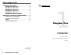
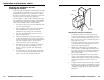
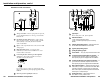
RGB 406 front and rear features
1
Auto power LED — If this LED is on, power and sync pulses
are present. If no sync is present, power and this LED turn off.
2
H. Shift (horizontal shift) control — This controls horizontal
centering. If output is SOG or if DIP SW1-2 (DDSP) is set to On,
the horizontal shift control is disabled.
3
Input — This 9-pin D-sub male connector is for RGB analog input.
4
Audio 3.5 mm stereo PC-type connector for unbalanced input —
See page 2-12 for an input plug wiring diagram.
5
High Z/75 Ohm switch — For proper video termination, set this
switch to 75 Ohms if no local monitor will be connected.
6
BNC output connectors — These 6 connectors are for video and
sync output. Connect the coaxial cables’ BNC connectors as shown
on page 2-6 for red, green and blue video output, and either
separate horizontal and vertical sync or composite sync.
7
J13 jumper — Pin 1 = +5V, pin 2 = -5V, pin 3 = ground.
8
Audio output 3.5 mm, 5-pole captive screw connector — The
label below this connector provides a wiring diagram for balanced
audio output.
9
SW1 DIP switches — 1. ON = Removes serration pulses.
2. ON = Enables Digital Display Sync Processing (DDSP).
10
J10 blue gain/peaking jumper — Settings are shown on the label
located below the circuit board.
11
J9 green gain/peaking jumper
12
J8 red gain/peaking jumper
13
Circuit board — Only key components are shown here.
14
Twisted-pair wires — Splice these wires to a 12 to 24VAC or VDC
power source.
2-7
Front and rear panel (circuit board) features
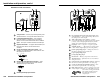
RGB 400 front and rear features
J10
J9
J8
RGB 406/
RGB 408
Captive
Screw
Connector
J13
33-398-01 B 08 99
J10
J8
J9
J10
J8
J9
ON
1 = +5V 20 mA max.
2 = –5V 20 mA max.
3 = Ground
SW1
321
1. ON = Remove
serration pulses.
2. ON = Digital
display sync.
.8V
.9V
.7V
.7V
.7V
.8V
.9V
V
H
CS
B
G
R
Extron
RGB 400
SW1
J11 J12
J13
ON
12
INPUT
H. SHIFT
HIGH Z
75 Ohm
AUTO POWER
123 4 567810 119
FRONT REAR
12
H
B
G
R
V
CS
2-6
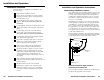
1
Auto power LED — If this LED (light-emitting diode) is on,
power and video sync pulses are present. If no sync pulse is
present,
power and this LED turn off.
2
H. Shift (horizontal shift) control — This controls horizontal
centering. If output is SOG or if DIP SW1-2 (DDSP) is set to On,
the horizontal shift control is disabled.
3
Input — This 9-pin D-sub male connector is for RGB analog input.
4
High Z/75 Ohm switch — For proper video termination, set this
switch to 75 Ohms if no local monitor will be connected.
5
BNC output connectors — These 6 connectors are for video and
sync output. Connect the coaxial cables’ BNC connectors as
shown here for red, green and blue video
output, and either separate horizontal and
vertical sync or composite sync.
6
J13 jumper — Pin 1 = +5V, pin 2 = -5V, pin 3 = ground.
7
SW1 DIP switches — 1. ON = Remove serration pulses.
2. ON = Enable Digital Display Sync Processing (DDSP).
8
J10 blue gain/peaking jumper — Settings are shown on the label
located below the circuit board.
9
J9 green gain/peaking jumper
10
J8 red gain/peaking jumper
11
Circuit board — Only key components are shown here.
12
Twisted-pair wires — Splice these wires to a 12 to 24VAC or VDC
power source.