User’s Guide RGB 580xi Universal Remote Interface with Audio and ADSP™ www.extron.com Extron Electronics, USA 1230 South Lewis Street Anaheim, CA 92805 800.633.9876 714.491.1500 FAX 714.491.1517 Extron Electronics, Europe Beeldschermweg 6C 3821 AH Amersfoort, The Netherlands +800.3987.6673 +31.33.453.4040 FAX +31.33.453.4050 Extron Electronics, Asia 135 Joo Seng Rd. #04-01 PM Industrial Bldg., Singapore 368363 +800.7339.8766 +65.6383.4400 FAX +65.6383.4664 © 2006 Extron Electronics.
Precautions Safety Instructions • English This symbol is intended to alert the user of important operating and maintenance (servicing) instructions in the literature provided with the equipment. This symbol is intended to alert the user of the presence of uninsulated dangerous voltage within the product's enclosure that may present a risk of electric shock. Caution Read Instructions • Read and understand all safety and operating instructions before using the equipment.
ᅝܼ乏ⶹ • Ё᭛ 䖭Ͼヺোᦤ⼎⫼᠋䆹䆒⫼᠋ݠЁ ᳝䞡㽕ⱘ᪡㓈ᡸ䇈ᯢDŽ 䖭Ͼヺো䄺ਞ⫼᠋䆹䆒ᴎݙ᳝ 䴆ⱘॅ䰽⬉य़ˈ᳝㾺⬉ॅ䰽DŽ ⊼ᛣ 䯙䇏䇈ᯢк • 䑩ㅸỀ䑩嬦嫿⡈⼆枼敆嬼䍇夤ㆁ㙊 ⫊₩⏍Ề䑩嬵㕏ɿ ֱᄬ䇈ᯢк • 䑩ㅸⷕ⪙⫊₩嬵㕏ᶧḦ⡈⭇㚦Ề䑩ɿ 䙉ᅜ䄺ਞ • 䑩ㅸⷕ徶⫉ᷨ␂⏍䑩ㅸ㉈⊘ᵋ䗅ㆁ㙊⫊₩ ⏍㐎ẝ嬵㕏ɿ 䙓ܡ䗑ࡴ • ᵎ壂Ề䑩嬦ᷨ␂⋃⒇㯢㙊㋩劑䗅₸ㅗ弾 ⇡嫿⡈澤Ḧ忀₎⊲斪ɿ 䄺ਞ ⬉⑤ • 嬦嫿⡈⌫倾Ề䑩ᷨ␂ᵋ㝈㕏䗅䑶㷑ɿ 嫿⡈⼆枼 Ề䑩㙊♱一䗅Ờ䑶䰼丠Ờ䑶ɿ 䩭ᵊ㚢一澠♱一澡㕰 ⫊₩嫿㓾澤ᵎ倾ᵎ䑩ㅗ崴弈 ɿ ᢨᥝ⬉⑤ • ᵻ⫊₩♱ḏ嫿⡈㈕㋊䑶㷑澤嬸㈕㋊ㆁ㙊嫿 ⡈⍏ㅗ㞍暣䑶㷑䗅䑶㷑一澤ㅗḼẖ㋦ⅱⵃ䑶䰼丠䗅 䑶㷑一ɿ ⬉⑤㒓ֱᡸ • ⣦Ⓟⵄ一澤 忀₎埬嵪嵐澤ㅗ愎䆪㉥⋌ɿ 㓈ᡸ • ㆁ㙊丵Ἧ⼆枼䑲嫥嬂䗅丵Ἧ᷻⎙弜垍ɿ 嫿⡈ 怩㯢㙊䑩ㅸ⌰Ḧ㘵㊣䗅昷ḷɿᵻ忀₎℻䋱大䑶⊲斪 ᵎ壂儫ⴲ嬖☿㆔⹁嫿⡈䘗⪑丵Ἧ嬦嫿⡈ɿ 䗮亢ᄨ • 㙊ᷜ嫿⡈㙻⠴ᵋ㙊彛栏㤾ㅗ⪕澤⫄ḭ㕰䑩㚦 敳㪣㙻㒐だ₄ḷ弈䀮ɿ ᵎ壂䑩Ḽẖᵝ壀㉢Ẑ彛 栏⪕ɿ 䫖⬉∴ • ᵎ㪤䞯䗅㘵㊣
Table of Contents Chapter 1 • Introduction .......................................................... 1-1 About the RGB 580xi ............................................................ 1-2 Features ...................................................................................... 1-2 Chapter 2 • Installation and Setup .................................... 2-1 Installation Overview ......................................................... 2-2 Under-desk/-table/-podium mounting .........................
Table of Contents, cont’d Optional Cable Cubby AAP Devices ............................ A-6 Optional RGB 580xi AAP Replacement Cables ...... A-6 RGB 580xi Remote Interface Appendix B • Mounting Template ...................................... B-1 Dimensions ............................................................................... B-2 All trademarks mentioned in this manual are the properties of their respective owners. 1 Chapter One Introduction About the RGB 580xi Features 68-536-01 Rev.
Introduction About the RGB 580xi The Extron RGB 580xi is an analog, remote-mountable computer video interface that can be installed in a location that is hidden from the user’s view. It features a 300 MHz (< -3 dB) video bandwidth. It accepts one analog computer video input (RGBHV, RGBS, RGsB, and RsGsBs) on a 15-pin HD female connector and one unbalanced stereo audio input on a 3.5 mm stereo female jack.
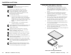
Installation and Setup Installation Overview CAUTION Installation and service must be performed by authorized personnel only. Under-desk/-table/-podium mounting 1. Attach the under-desk mounting brackets (part #70-077-01) to the interface with the six machine screws (provided in the mounting kit), as shown below. This procedure may also apply to table or podium mounting applications. See “Application Diagrams” in this chapter. 2.
Installation and Setup, cont’d Application Diagrams The RGB 580xi can be hidden from view and remotely connected to a computer through various Extron AAP and Cable Cubby (CC) AAP devices that are installed in office furniture or walls. Please consult with your Extron sales representative concerning these AAP and CC AAP devices and AAP-capable products from which devices may be installed. RGB 580xi CCSI AAP Audio Sound System 754 APA IER AMPLIF POWER H 2 1 S INP E U L T E C T .
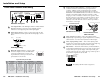
Installation and Setup Front Panel Features and Cabling 4 INPUTS AUDIO ANALOG CONTROL A B C D E SOG SERR DDSP V-SYNC WIDTH NEG SYNC COMP SYNC VIDEO OUTPUT LEVEL PEAKING RGB 580xi 1 2 3 5 4 6 7 Contact closure control connector — Connect an optional contact closure device to this female 5-pole captive screw connector. Making contact closure between pins A and B transmits a channel signal through the RS-232 port.
Installation and Setup, cont’d 1 — DDSP (Digital Display Sync Processing) — This feature may be necessary for digital display devices such as LCD, DLP (digital light processing) and plasma displays. Use this option if the image is not displayed properly after other options, such as serration pulse and vertical sync pulse width, have been explored. On — Rear Panel Features and Cabling 100-240 0.5A MAX. OUTPUTS R The interface uses DDSP instead of ADSP. DDSP does not process the sync signal.
Installation and Setup, cont’d Front Panel Adjustments Video signals passing through long cable runs (over 125 feet) can decrease in strength, creating signal loss. The longer the cable, the greater the cable resistance and capacitance, and the greater the level and peaking adjustments that will be required to compensate for the resultant signal loss. These adjustments change the level and peaking of the output signal to compensate for capacitance caused by up to 1000 feet (304.
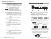
Installation and Setup, cont’d 2. Follow steps 3 through section of this chapter. in the Installation Overview 8 DDSP disables the horizontal shifting control. 5 AAP Device Features 3 4 3 AUDIO IN SHIFT AUDIO IN RGB 580xi AAP RGB 580xi S AAP COMPUTER IN Cabling the AAP Device Rear Connectors Extron’s various AAP devices for the RGB 580xi may come with several rear connectors that may require cabling.
Installation and Setup, cont’d RGB 580xi CCSI AAP LED connector (J2) — Insert wires into and tighten the screws on the 3.5 mm, 3-pole captive screw connector. This connector is used for powering the green and amber LEDs. Wire the connector as shown in the following illustration. H CC AAP Audio connector Audio output connector (J3) — Insert wires into and tighten the screws on the 3.5 mm, 3-pole captive screw connector. This connector is used for unbalanced stereo audio output.
Installation and Setup, cont’d To cable the captive screw connectors, refer to the following diagrams and orient the wires according to the view angle of the captive screws. Troubleshooting Turn on the input devices (computer, audio device) and output device(s) (projector, monitors, speakers). The image should now appear on the screen, and sound should be audible. J2 If the image does not appear or there is no sound 2 J4 SHIFT 1. Ensure that all devices are plugged in. 2.
Installation and Setup, cont’d 6. If the image still does not display correctly, call Extron’s S3 Sales & Technical Support Hotline.
Remote Control There are two ways to control the horizontal shifting feature of an RGB 580xi remote interface: by using the AAP horizontal shift (H. shift) control, or by using an RS-232 remote control device. RS-232 Programmer’s Guide The interface can be remotely controlled via a host computer attached to the rear panel’s 3-pole captive screw RS-232 connector.
3-4 RGB 580xi • Remote Control Display version (Ver x.xx) Display interface’s part # Display status X2 Control Software for Windows The included graphical control software for Windows offers another way to control the interface via RS-232 in addition to the Simple Instruction Set commands listed on page 3-4. The control software is compatible with Windows 3.1x, Windows 95/ 98, and Windows NT. The RGB 580xi uses version 2.
Remote Control, cont’d For information on program features, press the F1 computer key, click on the Help menu from within the control program, or double-click on the RGB 302+304 Help icon in the Extron Electronics group or folder. Contact Closure Remote Control For contact closure, connect a contact closure remote control device to the front panel’s contact closure female 5-pole captive screw connector.
Specifications, Parts, and Accessories Specifications Video — RGB 580xi Gain ................................................ 0.35 V to 1.45 Vp-p Bandwidth ..................................... 300 MHz (-3 dB) Video input — RGB 580xi Number/signal type ................... Connectors ................................... Nominal level ............................... Minimum/maximum levels ....... Impedance .................................... Horizontal frequency .................. Vertical frequency ........
Specifications, Parts, and Accessories, cont’d Control/remote — interface Serial control port ........................ Baud rate and protocol ............... Serial control pin configuration ... Program control .......................... RS-232, captive screw connector, 3 pole 9600 baud, 8 data bits, 1 stop bit, no parity 1 = TX, 2 = RX, 3 = GND Extron’s control/configuration program for Windows® Extron’s Simple Instruction Set (SIS™) General Power (RGB 580xi) .......................
Specifications, Parts, and Accessories, cont’d Optional Cable Cubby AAP Devices Description RGB 580xi Remote Interface Part number RGB 580xi CCS AAP 9' (black) 70-254-02 RGB 580xi CCS AAP 12' (black) 70-255-02 RGB 580xi CCSI AAP 9' (black) 70-256-02 RGB 580xi CCSI AAP 12' (black) 70-257-02 Optional RGB 580xi AAP Replacement Cables These cables apply only to the RGB 580xi AAP, RGB 580xi S AAP, and RGB 580xi SI AAP; they do not apply to the RGB 580xi CCS AAP or RGB 580xi CCSI AAP.
Dimensions for Mounting Dimensions For under-desk mounting, use the bracket mounting kit which is included with the RGB 580xi, and refer to the template illustration below. The template shown here is not drawn to scale and is to be used for dimensional reference only. 2.50" (6.35 cm) . Not Drawn to Scale 7.10" (18.