
User's Manual


4 IPATRLY4•Operation
Connections
N
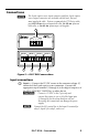
Figure 4 is a wiring diagram of a typical application: an Extron
IPA T RLY4 driving a screen controller. Please be aware that
these are examples only. Your equipment may have different
wiring requirments. Refer to the manual from the applicable
manufacturer for specific wiring instructions.
NO C NC
NO C NC NO C NC NO C NC
RELAY 1
RELAY 2
RELAY 3
RELAY 4
NO C NC
NO C NC NO C NC NO C NC
RELAY 1
RELAY 2
RELAY 3
RELAY 4
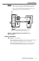
For a typical Stewart screen controller,
a momentary closure on relay 1, 2, or 3
causes the screen to move up, down,
or stop.
UP DOWN STOP
Typical Stewart Low Voltage Controller
COMMON
RED BLACK
Typical Da-Lite or Draper Low Voltage Controller
WHITE (DA-LITE)
BLUE (DRAPER)
IPA T RLY4
NOTE
For a typical Da-Lite or Draper screen controller,
a momentary closure on relay 1 or 2 causes the
screen to move up or down. A momentary
closure on relay 3 causes the screen to stop in
its current position. Use 1N4001 or equivalent
diodes (not included) for reverse bias protection.
Recommended diode specifications:
100 mA maximum through diode
50 V maximum reverse bias
NOTE
IPA T RLY4
Figure 4 — Wiring diagram for connection to a screen
controller
Operation
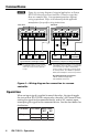
When an input signal is applied to one of the relays, the signal toggles
the state of that IPA T RLY4’s output relay; the relay’s NO contacts close,
routing the signal for the connected device, and its NC contacts open,
interrupting the signal for the connected device. See the chart below for
clarification.
I/O state Relay state
NCNO
Output
On (closed) Closed Open
Off (open)
Open Closed
I/O mode