User’s Manual SCREEN POSITION DOWN STOP UP RCM-SC ROOM CONTROL SCREEN POSITION LIGHTING ON / OFF RCM-SCLT Relay Control Modules Control Accessories www.extron.com Extron Electronics, USA Extron Electronics, Europe Extron Electronics, Asia Extron Electronics, Japan 1230 South Lewis Street Anaheim, CA 92805 USA 714.491.1500 Fax 714.491.1517 Beeldschermweg 6C 3821 AH Amersfoort The Netherlands +31.33.453.4040 Fax +31.33.453.
Precautions Safety Instructions • English This symbol is intended to alert the user of important operating and maintenance (servicing) instructions in the literature provided with the equipment. This symbol is intended to alert the user of the presence of uninsulated dangerous voltage within the product's enclosure that may present a risk of electric shock. Caution Read Instructions • Read and understand all safety and operating instructions before using the equipment.
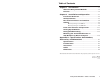
Table of Contents Chapter 1 • Introduction .......................................................... 1-1 About the Relay Control Modules ................................. 1-2 Features ...................................................................................... 1-2 Chapter 2 • Installation and Operation ......................... 2-1 Installation Overview .......................................................... 2-2 UL Requirements .................................................................
Table of Contents, cont’d Relay Control Modules 1 Chapter One Introduction About the Relay Control Modules Features ii Relay Control Modules • Table of Contents
Introduction About the Relay Control Modules The Extron Relay Control Modules (RCMs) are hard-wired remote control keypads designed for use with the Extron MediaLink Controller (MLC). Refer to the MediaLink Controllers User’s Manual for information on installing, operating, and setting up the controller. All setup must be done via RS-232. See chapter two and refer to the MediaLink Control Program or the MediaLink Controllers User’s Manual for details.
Installation and Operation Installation Overview CAUTION Installation and service must be performed by authorized personnel only. These products should be used with UL approved electrical boxes. See “UL Requirements”, page 2-3. To install and set up Relay Control Modules, follow these steps: 1 Turn the equipment off. Make sure that the control module(s) and the MediaLink Controller (MLC) are disconnected from the power source.
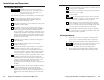
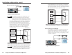
Installation and Operation, cont’d Rear Panel Connectors and Switches For each control module to be connected to an MLC, set the rear panel DIP switches, then follow these steps: 1 1 A B C D E A B C D E 1 2 ON 2 The same type and quantity of connectors and DIP switches shown above can be found on the rear panels of all models of the control modules. 1 Cabling 1.
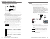
Installation and Operation, cont’d 5. A B C D E A B C D E Plug one end of the cable into the control module’s remaining communications connector, and plug the other end into a communications connector on the next control module. The photo below shows control modules (RCM, IRCMs, and/or ACMs) connected to an MLC in a typical daisy chain setup.
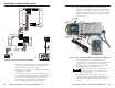
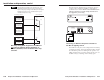
Installation and Operation, cont’d MLC relay wiring for an RCM-SC For Stewart Filmscreen screen controllers, a momentary closure between the up and common terminals, the down and common terminals, or the stop and common terminals will cause the screen to go up, go down, or stop.
Installation and Operation, cont’d The diagrams included here are examples only. Your equipment may have different wiring requirements. Refer to the specific wiring instructions provided by the manufacturer of the screen controller and AC power controller that you are using. Low Voltage Controller Red (Da Lite/Draper) Up (Stewart) The following two illustrations give examples of how to connect a relay controller to the MLC to turn lights or another device on and off.
Installation and Operation, cont’d Front Panel Features and Operation 120 VAC 50/60 Hz MAX LOAD 15 A SCREEN POSITION DOWN ROOM CONTROL STOP UP SCREEN POSITION LIGHTING C ON / OFF LISTED 7Z37 PROFESSIONAL AUDIO EQUIPMENT MINIPORT-15 POWER RELAY CLASS2 WIRING +12VDC 6Ma MAX STATUS REM GND POWER DELAY OUT 3A RCM-SC Front 1 2 1 1 3 RCM-SCLT Front 1 Screen Position Up ( )/Down ( ) buttons — These buttons can be set up (via the control software) to toggle the screen to move up or down.
Installation and Operation, cont’d Testing/Troubleshooting Before installing the control modules into the wall or furniture, test the system to make sure that the connections are correct and the modules are working correctly. 4. 6. Connect the cables between the MLC and the control module(s), connect IR Emitters or an IR Broadcaster to the MLC (if IRCM modules are used), and connect a host computer to the MLC’s Config port.
Installation and Operation, cont’d All IR control signals are sent to all devices (video sources, projector, etc.) at the same time even if two or three IR Emitters or an IR Broadcaster are installed. The IR sending devices share the same IR Display/Control port on the MLC. • For RCM modules, ensure that the wiring from the MLC to the screen motor’s low voltage controller is correct. Refer to the screen manufacturer’s user’s guides.
Specifications, Part #s, Accessories, Dimensions Specifications Included Parts These items are included in each order for a control module: General Power ............................................. 12VDC from the MLC 206 Temperature/humidity .............. Storage -40° to +158°F (-40° to +70°C) / 10% to 90%, non-condensing Operating +32° to +122°F (0° to +50°C) / 10% to 90%, non-condensing Rack mount ...................................
Specifications, Part Numbers, Accessories, cont’d Dimensions The following diagrams have been reduced to fit on the page. All dimensions are given in inches. The symbol “ø“ indicates a diameter. RCM dimensions .363 .182 .160 DETAIL A +.000/ Ø.160-.010 max. extrusion around stud on far side, +.003/ +.003/ Ø.112-.000 thru (4 places). Ø.166-.000 thru (2 places). PEM insert BSOS-440-16 or equiv. Insert from near side. 2.900 PEM insert FHS-440-6 or equiv. Insert from near side. (4 req'd) +.000 1.390-.