
- Extron Electronics User's Manual switch

Relay Control Modules • Installation and Operation
Relay Control Modules • Installation and Operation
Installation and Operation, cont’d
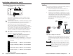
The diagrams included here are examples only. Your
equipment may have different wiring requirements.
Refer to the specific wiring instructions provided by the
manufacturer of the screen controller and AC power
controller that you are using.
1B
2A
1A
2B
3A
3B
Up
MLC Relay PortsLow Voltage Controller
Down
AC Power Controller
12VDC
Common
Red
(Da Lite/Draper)
Up (Stewart)
Black
(Da Lite/Draper)
Down (Stewart)
White (Da Lite)
Blue (Draper)
Common
(Stewart)
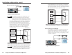
MLC relay wiring block diagram for an RCM-SCLT
and a Da Lite (#40973), Draper (#6300858), or
Stewart (#6300891) screen controller and a relay
controller
The following two illustrations give examples of how to
connect a relay controller to the MLC to turn lights or
another device on and off. Refer to the manual that came
with the controller for specific wiring information for
the equipment you are using.
110 VAC/1200W
110 VAC
50/60 HZ
CONTROL
1 2 3 4
3A
3B
AC1
OFF
ON
1 2 3 4
MLC Relay Port
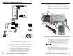
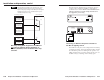
Connecting an AMX PC-1 AC power controller to
the MLC for lighting control
The AMX PC-1 relay box can be configured for momentary
or latching operation. All front panel DIP switches should
be in the down position for latching mode operation. See
AMX’s instructions if you need to change modes. Also set
the MLC’s relay to “latching” and “normally open”.
2-10 2-11