
- Extron Electronics User's Manual switch

Relay Control Modules • Installation and Operation
Relay Control Modules • Installation and Operation
Installation and Operation
2-3
Installation Overview
CAUTION
Installation and service must be performed by
authorized personnel only. These products should
be used with UL approved electrical boxes. See
“UL Requirements”, page 2-3.
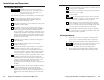
To install and set up Relay Control Modules, follow these steps:
1
Turn the equipment off. Make sure that the control
module(s) and the MediaLink Controller (MLC) are
disconnected from the power source.
2
Run cables through the wall or furniture where the control
module(s) will be installed.
3
If applicable, follow the site preparation (hole cutting,
electrical box or mud ring/mounting bracket installation,
and cable preparation) instructions included with the
device, faceplate, or AAP wall plate into which the control
module will be installed. Cable clamps should be used to
hold the cables in place for strain relief. Trim back and/or
insulate exposed cable shields with heat shrink to reduce
the chance of short circuits.
4
Attach the control module(s) to the Extron faceplate(s) or
AAP wall plate(s).
5
Set the identification DIP switches on each control
module’s circuit board.
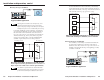
6
Connect daisy-chained control modules to each other (if
applicable). Wire the 3.5 mm, 5-pole captive screw
connectors on both ends of each cable that will connect
one control module to another. Plug the wired connectors
into the receptacles on the back of the control modules.
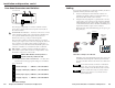
7
Connect the control module(s) to the MLC. At the control
module end of the cable, wire the connector that will
attach the MLC to the control module(s). Plug the wired
connector into the receptacles on the back of the control
module(s), and insert and fasten the wires to the
appropriate pins of the MLS/Power port on the bottom of
the MLC.
8
Connect the projector’s RS-232 port to the MLC’s Display/
Source Control RS-232 port (refer to the MediaLink
Controllers User’s Manual). If infrared control modules
(IRCMs) are part of the system, connect IR Emitters or an
IR Broadcaster to the MLC’s Display/Source Control IR
port.
2-2
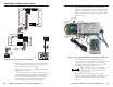
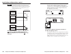
9
Connect a MediaLink Switcher (MLS) to the MLC 206 and
to the projector, if applicable.
10
Restore power to the MLC, and connect the optional MLS
switcher to a power supply.
11
Set up the MLC.
The setup/configuration requires an RS-232 connection
to the MLC’s Config port. Setup should be done before
the MLC is installed into the wall or furniture.
12
Press a button on each control module. If the expected
action (a lighting or screen position change, for example)
doesn’t occur, disconnect power from the MLC and verify
correct connector wiring at both ends of the cable(s).
13
Mount the MLC and the faceplate/wallplate containing
the control module(s) into the wall/furniture. Make sure
that the faceplate is grounded.
UL Requirements
1. These units are not to be connected to a centralized DC
power source or used beyond their rated voltage range.
2. These units must be installed in UL listed junction boxes.
The UL approved electrical wall box (junction box) is not
included with the control module; the installer is
responsible for obtaining and installing the box.
3. These units must be installed with accordance with the
National Electrical Code and with local electrical codes.