
- Extron Electronics User's Manual switch

Relay Control Modules • Installation and Operation
Relay Control Modules • Installation and Operation
Installation and Operation, cont’d
Cabling
For each control module to be connected to an MLC, set the rear
panel DIP switches, then follow these steps:
1. If it hasn’t already been done when the wall box was
installed, cut a length of Extron Comm-Link cable to go
between the MLC and the control module.
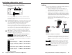
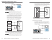
2. Using the following diagram as a guide, attach a 3.5 mm,
5-pole captive screw connector to the end of the cable that
will be plugged into the control module, and connect wires
on the other end of the cable to the MLC’s IR/RCM port (a
4-pole direct insertion captive screw connector).
Wire both ends of the cable identically (pin A to pin A, pin
B to pin B, etc.).
MLC
IR
/
RCM
port
ABCD
IR
/
RCM
RCM Control
Module(s)
ABCDE
Control
Module
connector
C
C
+12VDC
Control signal (RCM/
IRCM)
Ground ( )
B
B
A
A
MLC 206 to a Relay Control Module
MLC 206
Extron
MediaLink Controller
MLC 206
DISPLAY
POWER
VOLUME
MAX/
MIN
VCR DVD Laptop
ROOM CONTROL
SCREEN POSITION LIGHTING
ON / OFF
Only three wires are required, but use four wires (A, B, C, D)
if an IR Link infrared repeater will be daisy chained with
the control modules. Refer to the IR Link User’s Manual for
details.
Do not install more than one IR Link in a MediaLink
system. Also, do not connect more than four control
modules (RCMs, ACMs, IRCMs) at a time to an MLC.
The MLC contains three relays, so you may install a
maximum of one RCM-SC or one RCM-SCLT in a
system with an MLC.
ADBC E ADBC E
ON
12
1 1
2
2-5
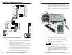
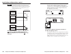
Rear Panel Connectors and Switches
2-4
The same type and quantity of connectors and DIP switches
shown above can be found on the rear panels of all models of
the control modules.
1
Communications connectors — Use these connectors to connect
control modules together and to connect them to the MLC and
to an optional IR Link infrared repeater. Both connectors
function the same way, so they are interchangeable.
Plug one end of an Extron Comm-Link cable into one of these
3.5 mm, 5-pole captive screw connectors, and plug the other end
into a connector on another control module or an IR Link, or
connect those wires to the direct insertion IR/RCM captive screw
connector of an MLC. Do not install more than one IR Link.
2
DIP switches — Set these switches to identify the address of
each module. Each module must have a unique address. Note
the direction of the arrow on the switch.
ON
1234
ON
12
Address DIP switches can be 4-position or
2-position, but only 1 and 2 are used.
1, 2 — Control module address identification — See the follow-
ing illustrations for the appropriate settings for each address.
3, 4 — Not used
ON
12
1 and 2 down (off) = address 0, control module #1
ON
12
ON
12
ON
12
1 up (on), 2 down (off) = address 1, control module #2
1 down (off), 2 up (on) = address 2, control module #3
1 up (on), 2 up (on) = address 3, control module #4
DIP switch settings