
- Extron Electronics User's Manual switch

Relay Control Modules • Installation and Operation
Relay Control Modules • Installation and Operation
Installation and Operation, cont’d
ADBC E ADBC E
ON
12
ADBC EADBC E
MLC
IR
/
RCM
port
ABCD
IR
/
RCM
RCM
Control
Module
Control
Module
Control Module
Control Module
C
C
+12VDC
Control signal (RCM/
IRCM)
Ground ( )
B
B
A
C
B
A
A
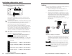
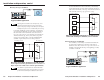
MLC 206 to a daisy chain of Control Modules
MLC 206
Extron
MediaLink Controller
MLC 206
DISPLAY
POWER
VOLUME
MAX/
MIN
VCR DVD Laptop
DVD CONTROL
PLAY NEXT PAUSE STOP
Tx
REW
ENTER
TITLE
MENU
ROOM CONTROL
SCREEN POSITION LIGHTING
ON / OFF
Connectors are included with each control module, but the
cable must be purchased separately. See appendix A for
cable part numbers and conductor gauges.
3. Plug the 5-pole connector into one of the control module’s
communications connectors.
4. Cut a cable and attach 5-pole connectors to both ends of it
for each additional control module that will be connected
in a daisy chain. Wire both ends of the cable identically
(pin A to pin A, pin B to pin B, etc.). Up to a total of 4
control modules in any combination of models can be
daisy chained together and connected to the MLC.
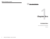
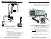
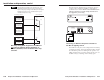
5. Plug one end of the cable into the control module’s
remaining communications connector, and plug the other
end into a communications connector on the next control
module. The photo below shows control modules (RCM,
IRCMs, and/or ACMs) connected to an MLC in a typical
daisy chain setup.
A daisy chain of control modules connected to an MLC 206
6. Connect the MLC’s rear/bottom panel relay ports to a
screen controller or a relay controller (A/C trigger box) if it
is appropriate for your installation. Use the following
block diagrams as a general reference, and refer to the
wiring diagrams that came with the screen.
The MLC contains three relays, so you may install a
maximum of one RCM-SC or one RCM-SCLT in a
system with an MLC.
Many different brands and models of low voltage
controllers can be used with the MLC and RCM to control
screen movement. A few examples are given on the
following pages, but different models require different
wiring.
To 1–2 additional
Control Modules
(IRCMs, ACMs, RCMs)
IR Link Infrared Repeater
rear view
IR Emitter
(Connect 1 per
each IRCM.)
Control Module #1
rear view
MLC 206 rear view
Control Module #2
rear view
To an
MLS
switcher
RS-232
projector
connection
MLM faceplate
2-72-6