User’s Manual SCP/AAP A, SCP 200, SCP 250 Control Pads for Use With System Switchers www.extron.com Extron Electronics, USA Extron Electronics, Europe Extron Electronics, Asia Extron Electronics, Japan 1230 South Lewis Street Anaheim, CA 92805 USA 714.491.1500 Fax 714.491.1517 Beeldschermweg 6C 3821 AH Amersfoort The Netherlands +31.33.453.4040 Fax +31.33.453.4050 135 Joo Seng Road, #04-01 PM Industrial Building Singapore 368363 +65.6383.4400 Fax +65.6383.
Precautions Safety Instructions • English This symbol is intended to alert the user of important operating and maintenance (servicing) instructions in the literature provided with the equipment. This symbol is intended to alert the user of the presence of uninsulated dangerous voltage within the product's enclosure that may present a risk of electric shock. Caution Read Instructions • Read and understand all safety and operating instructions before using the equipment.
Table of Contents Chapter 1 • Introduction .......................................................... 1-1 About the SCP/AAP A, SCP 200, and SCP 250 .......... 1-2 Features ...................................................................................... 1-2 SCP 200 and SCP 250 feature ................................................ 1-2 Chapter 2 • Installation and Operation ......................... 2-1 Installation Overview ..........................................................
Table of Contents, cont’d SCP/AAP A, SCP 200, SCP 250 All trademarks mentioned in this manual are the properties of their respective owners. 68-511-01 Rev.
Introduction, cont’d Introduction About the SCP/AAP A, SCP 200, and SCP 250 The Extron SCP/AAP A, SCP 200, and SCP 250 are hardwired remote control keypads designed for use with Extron system switchers. Refer to the appropriate switcher’s user’s manual for information on installing, operating, and setting up the switcher. The system switcher cannot be configured from any of the SCP control pads. All switcher setup must be done from the switcher’s front panel or via RS-232.
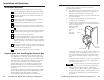
Installation and Operation, cont’d Installation and Operation Installation Overview To install and set up an SCP control pad, follow these steps: electrical wall box to allow room for the raised areas surrounding the knockouts. 1. Cut out the center portion of the template. Cut up to the dashed line if using an electrical box, or cut up to the dotted line if an electrical box will not be used. Run cables through the wall or furniture where the SCP will be installed. 2.
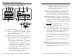
Installation and Operation, cont’d Rear Panel Connectors and Switches 1 1 1 J1 J2 1 3 8 7 6 5 4 3 2 1 2 J2 1 If this SCP is at the end of a daisy chain of SCPs, do not use the other connector. If this SCP is in the middle of a chain of SCPs, plug one end of a Comm-Link cable into the second captive screw connector, and plug the other end into the next SCP further away from the switcher. 2 DIP switches — Set these switches to indicate what model of system switcher the SCP is attached to.
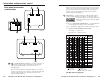
Installation and Operation, cont’d Cabling For each SCP to be connected to a system switcher, set the rear panel DIP switches, then follow these steps: 1. If it hasn’t already been done when the wall box was installed, cut a length of Extron Comm-Link cable to go between the switcher and the SCP. 2. Using the diagrams below as a guide, attach a 3.5 mm, 5-pole captive screw connector to each end of the cable. Wire both ends of the cable identically (pin A to pin A, pin B to pin B, etc.). 3.
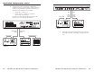
Installation and Operation, cont’d Another device such as an interface or distribution amplifier can receive power from the system switcher via an SCP, as long as the following limits for the total load attached to each switcher are not exceeded: 6. • System 7SC — 12VDC, 1 A • System 5cr Plus — 12VDC, 0.5 A (500 mA) (each port provides 250 mA) Plus ROOM POWER DISPLAY MUTE AUDIO MODE PC1 PC2 VID INPUT3 VID1 AUDIO VID2 Y/C VID VID PC Y/C Y/C PC1 INPUT COMPUTER MAX. CLIP MIN.
Installation and Operation, cont’d Mode button — For the System 5cr Plus, this button can be programmed to switch the mode of the projector between computer-video (RGB), S-video, and composite video. For the System 7SC, this button can be programmed to execute any RS-232 or IR command. Front Panel Features and Operation 2 4 5 6 2 3 4 IR DISPLAY POWER MUTE AUDIO 3 Volume control knob and LED — Turn this knob to adjust the audio volume.
Installation and Operation, cont’d Testing/Troubleshooting Before installing the control pad into the wall or furniture, test the system to make sure that the connections are correct and the SCP is working correctly. 1. Connect the cables between the switcher and the SCP(s). 2. Power on the switcher. 3. Press the input selection buttons or Show Me button on the SCP, and watch the LEDs on the switcher to see if the system switches to the desired input(s).
Installation and Operation, cont’d SCP/AAP A, SCP 200, SCP 250 A Appendix A Specifications, Part Numbers, and Accessories Specifications Included Parts Accessories Cables 2-14 SCP/AAP A, SCP 200, SCP 250 • Installation and Operation
Specifications, Accessories, Part Numbers, cont’d Specifications Control/remote — control pads IR controller module ................... IR 701 (optional) General Power ............................................. 12VDC, at 60 mA, from the System 7SC or System 5cr Plus switcher Temperature/humidity .............. Storage -40° to +158°F (-40° to +70°C) / 10% to 90%, non-condensing Operating +32° to +122°F (0° to +50°C) / 10% to 90%, non-condensing Rack mount ...................................
Specifications, Accessories, Part Numbers, cont’d Included Parts These items are included in each order for an SCP control pad: Included parts (SCP/AAP A) Part number SCP/AAP A (gray, black, white) 60-339-01, -02, -03 3.5 mm, 5-pole captive screw connectors Included parts (SCP 200) SCP 200 (gray, black, white) 10-319-10 Part number 60-338-01, -02, -03 2-gang electrical box 3.
+ .005 1.800 3.600 DETAIL A MILLED POCKET + .005 0.060" – .000 DEEP WITH R 0.031 FILLET ON TOP EDGE. BORE ø 0.313 x 0.070 – .000 DEEP, FLAT BOTTOM, FROM FAR SIDE (2 PLACES) 3.740 1.870 0.310 DETAIL A R 0.250 (4 PLACES) SCP 200 'b' 'a' 'b' ø 0.160 THRU WITH ø 0.290 X 82˚ C'SINK (4 PLACES) CODED 'a' 3.500 3.250 AUDIO VOLUME 'a' 1.545 IR 'a' 'a' 'b' 'b' 0.000 .500 0.609 1.005 1.355 1.855 2.430 2.930 3.495 3.280 3.891 4.500 ø 0.125 THRU WITH 0.
SCP/AAP A, SCP 200, SCP 250 • Dimensions, Templates, Labels DISPLAY MUTE 0.000 2.700 DETAIL A 5.400 + .005 MAX/ MIN 1.985 MODE 1.985 VOLUME AUDIO 3.785 IR .240 + .005 – .000 4.985 4.997 .480 R .062 (4 PLACES) 4.685 DEEP WITH R 0.031 FILLET ON TOP EDGE. MILLED POCKET 0.060" 2.770 2.585 2.585 BORE ø 0.313 x 0.070 – .000 DEEP, FLAT BOTTOM, FROM FAR SIDE (2 PLACES) 5.540 0.000 POWER SCP 250 6.385 .166 .185 .331 DETAIL B .371 DETAIL B DETAIL A 2.850 SCP 250 dimensions 0.310 .
Dimensions, Templates, and Labels, cont’d SCP 200 template Templates Use the templates as a guide to mark and cut the hole in the wall or furniture through which the SCP control pad will be installed. The templates include the recommended 0.1” (0.25 cm) clearance on all sides of the electrical wall box to allow room for the raised areas surrounding the knockouts. See the installation chapter for details on installing the control pads.
Dimensions, Templates, and Labels, cont’d SCP 250 template Labeling Buttons on the SCPs B-8 The SCP 200 and SCP 250 have translucent panels (“windows”) behind which customized labels can be inserted. To remove a panel, 1. Insert the head of a small Phillips screwdriver into the hole in one end of the panel. 2. Gently slide the tab on the edge of the panel out of the recess in the SCP’s faceplate. Premade templates and blank templates for the SCPs’ label windows are printed in this chapter.
Dimensions, Templates, and Labels, cont’d 4. Cut the label strips to the appropriate length, and install them in the SCP’s windows. For information about using the program, you can access a help file by clicking on the Help menu on the main screen and choosing Show Help. You can also see an example of a completed Button-Label Generator window by clicking on the Help menu on the main screen, choosing Show Help, and clicking on the Load Demo button.
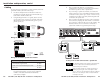
Dimensions, Templates, and Labels, cont’d n/a SCP 250 labels B-12 SCP/AAP A, SCP 200, SCP 250 • Dimensions, Templates, Labels 1 2 3 SCP/AAP A, SCP 200, SCP 250 • Dimensions, Templates, Labels ROOM For use with a System 5cr Plus switcher ROOM 2 ROOM 1 For use with a System 7SC switcher 1 2 4 3 5 4 5 n/a 6 n/a 7 This page is left intentionally blank.
Dimensions, Templates, and Labels, cont’d This page is left intentionally blank.