User’s Guide V-Lock™ Wall Mount Assembly Kit ® Replacement accessory for Extron System INTEGRATOR SI 26 and SI 28 Surface Mount Speakers 68-1364-01 Rev.
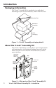
Introduction Packaging Information The V-Lock™ Assembly Kit is supplied as two individual mounting kits (one in each inner box), and an Allen hex tool. Allen Hex Tool Wall Mount Assemblies Outer Packaging Figure 1 — V-Lock™ Assembly packaging details About the V-Lock™ Assembly Kit The V-Lock™ Wall Mount Assembly Kit is a pair of replacement wall mounting kits (wall plate and locking stage only) for the Extron System INTEGRATOR® SI 26 and SI 28 two-way surface mount speakers.
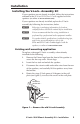
Installation Installing the V-Lock™ Assembly Kit If your speakers are not already installed, follow the instructions outlined in the SI 26 and SI 28 User's Guide supplied with the speakers (or online at www.extron.com). If your speakers are already installed, replace the V-Lock™ assembly by following the instructions, below. N Referring to packaging information for location, carefully remove and check contents before installation.
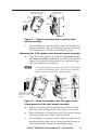
Installation, cont'd 5. Carefully remove (and retain) the mounting screws, taking care not to damage the mounting holes in the wall. Remove the mount from the wall. 6. Remove a new V-Lock™ assembly from its box, loosen the hex cap screw and rotate the front section approximately 90 degrees to the mounting plate, (see figure 3). Lightly tighten the hex cap screw to temporarily lock it in position, allowing access to the mounting holes in the wall plate. 7.
...and slide it down into the V-lock groove. Lift the speaker up to the wall mount assembly.... Box Bracket V Lock Groove Box Bracket V Lock Groove Figure 5 — Slide the speaker down onto the wall mount assembly If re-installing two speakers, repeat all the installation and speaker mounting steps for the second speaker, then go to "Final adjustments" section on the following page. 2. Mounting the SI 28 speaker onto the wall mount assembly 1a.
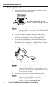
Installation, cont’d Final adjustments 1. When the speaker is in place, insert the audio wires into the back of the speaker as shown. Extron Negative Wire INPUT Push down on the spring terminals at the back of the speaker, and insert the wires. Release the springs to secure. Positive Wire Figure 7 — Insert audio wires into the terminals N If the ends of the wires are damaged and need to be restripped, follow the instructions in the SI 26 and SI 28 User's Guide. 2.
Extron’s Warranty Extron Electronics warrants this product against defects in materials and workmanship for a period of five years from the date of purchase.
www.extron.com Extron Electronics, USA 1230 South Lewis Street Anaheim, CA 92805 800.633.9876 714.491.1500 FAX 714.491.1517 Extron Electronics, Europe Beeldschermweg 6C 3821 AH Amersfoort, The Netherlands +800.3987.6673 +31.33.453.4040 FAX +31.33.453.4050 Extron Electronics, Asia 135 Joo Seng Rd. #04-01 PM Industrial Bldg., Singapore 368363 +800.7339.8766 +65.6383.4400 FAX +65.6383.4664 © 2007 Extron Electronics. All rights reserved.