SW AV Series Video and Audio Switchers 68-644-01 Rev.
Precautions Safety Instructions • English Warning This symbol is intended to alert the user of important operating and maintenance (servicing) instructions in the literature provided with the equipment. Power sources • This equipment should be operated only from the power source indicated on the product. This equipment is intended to be used with a main power system with a grounded (neutral) conductor. The third (grounding) pin is a safety feature, do not attempt to bypass or disable it.
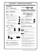
Quick Start — SW AV Series Switchers Installation 5 Step 1 — Power down 9 6 Female Turn off power to the input and output devices, and remove the power cords from them. Step 2 — Mounting If desired, mount the switcher in a rack or under a table. Step 3 — Inputs As applicable to your switcher, connect: a Up to 4, 6, 8, or 12 S-video inputs to the Input connectors. — or — b Up to 4, 6, 8, or 12 composite video inputs to the Input connectors.
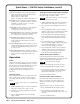
Quick Start — SW AV Series Switchers, cont’d Audio level indicators (Input 1 through Input 4 LEDs) each indicate a range of 6dB when lit: Input 1 LED: off = 0 db to 5dB, Input 1 LED: lit = 6dB to 11dB, Input 1 and 2 LED:lit = 12dB to 17dB, and so on. Mode button (video switchers) is used with the Normal, Auto, or Executive button to select the switching or executive mode. A secondary function of the Input 1 button. Normal button (video switchers) is used with the Mode button to select normal mode.
Table of Contents Chapter 1 • Introduction ....................................................................................................... 1-1 About the Switchers ......................................................................................................... 1-2 Features ................................................................................................................................... 1-2 Video switchers ......................................................................
Table of Contents, cont’d Front Panel Operations .................................................................................................... 3-6 Power ................................................................................................................................. 3-6 Switching inputs ................................................................................................................ 3-6 Example 1: Select an input .........................................................
SW AV Series Switchers 1 Chapter One Introduction About the Switchers Features
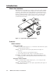
Introduction, cont’d Introduction About the Switchers The Extron SW AV series (figure 1-1) is a family of video and/or audio switchers with a wide array of input and output configurations, video formats, and audio connections. The switchers route S-video (luminance (Y) and chrominance (C)), and/or composite video, and/or unbalanced audio on RCA connectors, and/or balanced or unbalanced audio on captive screw connectors.
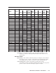
Inputs Model Part # SW 4AV 60-484-21 SW 4AV RCA SW 4SVA Outputs Captive Captive RCA RCA Video S-video screw Video S-video screw audio audio audio audio 4 No 4 60-484-31 4 No 60-484-22 No 4 No 2 No 2 No 4 2 No 1 1 4 No 1 1 2 No No SW 4SVA RCA 60-484-32 No 4 No 4 1 1 1 1 SW 6V 60-487-01 6 No No No 2 No No No SW 6AV 60-487-21 6 No 6 No 2 No 2 No SW 6AV RCA 60-487-31 6 No No 6 2 No 1 1 SW 6SV 60-487-02 No 6 No No 1 1 No No SW 6SVA
Introduction, cont’d External sync input and output connectors — Allow the switcher to use a black burst (genlock) signal to synchronize switching during the vertical interval. This ensures glitch-free switching among multiple timed sources. Audio switchers Captive screw connector (A) models Inputs — These switchers input 4, 6, 8, or 12 balanced or unbalanced stereo audio signals, on 3.5 mm, 5-pole captive screw terminals.
Audio follow — If the switcher is also a video model, audio can be switched with the corresponding video input. Audio follow switching can be done via front panel control or under RS-232 remote control. Audio breakaway — If the switcher is also a video model, audio can be broken away from its corresponding video input signal. Audio breakaway switching can be done via front panel control or under RS-232 remote control.
Introduction, cont’d 1-6 SW AV Series Switcher • Introduction
SW AV Series Switchers 2 Chapter Two Installation Installation Overview Mounting the Switcher Cabling and Rear Panel Views
Installation, cont’d Installation Installation Overview To install an SW AV Series switcher, do the following: 1 Turn off the input and output devices, and unplug their power cords. 2 If desired, mount the switcher in a rack or under furniture (see Mounting the Switcher below). 3 Connect the input and output devices to the switcher (see Cabling and Rear Panel Views on page 2-3).
Mounting Screws (2 Plcs) Each Side Drill pilot holes — 3/32” (2.4mm) diam. 1/4” (6.3 mm) deep Rack-mount Bracket RS UT 2 23 A TP SW 12SVA RCA OU or UTR B TP OUL L R 11 12 10 11 UTS INP 10 9 8 7 6 5 5 4 4 3 L NC 3 SY 2 D UTS TE LIS 23 1T.E. I.T TP OU US R 1 C 11 9 A 7 TS PU IN 5 12 3 B 10 8 1 A 0.3 6 V 40 0-2 10 4 2 01 REV. A 2- - 75 33 Hz #8 Screw (4 Plcs) Each Side Table/ Wall-mount Bracket -60 50 Figure 2-1 — Mounting the switcher 3.
Installation, cont’d 1 12 3 10 3 11 9 5 7 Figure 2-2 — SW 4AV composite video switcher with audio 2 12 3 10 4 11 9 6 8 7 Figure 2-3 — SW 12SVA RCA S-video switcher with audio on RCA connectors Video input and output connections (video models only) 1 Composite video inputs (composite video (V) switchers only) — For each input, connect a composite video source to one of these BNC connectors.
Figure 2-4 shows three methods of wiring the captive screw audio connectors for input and figure 2-5 shows two methods of wiring the connectors for output. A mono audio connector consists of the tip and sleeve. A stereo audio connector consists of the tip, ring and sleeve. If wiring a captive screw connector from an existing unbalanced audio cable, the white insulated wire is typically the left channel (tip) and the red insulated wire is typically the right channel (sleeve).
Installation, cont’d 8 RCA connector audio output (RCA connector audio (A RCA) models only) — The switcher has a pair (left and right) of RCA connectors for an unbalanced stereo audio output. Remote connection 9 RS-232/Remote connector — Connect a host device, such as a computer or touch panel control, or an IR remote control or a remote contact closure device (SW 4 and SW 6 models only) to the switcher via this 9-pin D connector (figure 2-6) for remote control of the switcher.
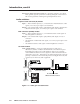
Timing Source OUT OUTPUTS SYNC A IN B OUT INPUTS 1 L R 2 L 3 L R R 4 L R SW 4AV Rear Panel To next device or terminate. IN Figure 2-7 — Simple external sync connection example Figure 2-8 shows another configuration, in which the timing source passes through three video cameras and a video scan converter before connecting to the switcher. This type of video camera is capable of synchronizing with the external timing source for video editing applications.
Installation, cont’d 2-8 SW AV Series Switchers • Installation
SW AV Series Switchers 3 Chapter Three Operation Front Panel Controls and Indicators Front Panel Operations Optimizing the Audio (Audio Switchers) Troubleshooting — If No Image Appears
Operation, cont’d Operation Front Panel Controls and Indicators The family of SW AV switchers have a wide variety of input buttons and other controls and LEDs that vary with the number of inputs and whether the switcher has video, audio, or both. Not all switchers have every control or indicator described in this chapter. The table at the bottom of this page identifies the control and indicator groups that are present on each switcher in the SW AV Series.
• Audio switcher — Switches audio on captive screw or RCA connectors. May or may not include video switching. • Audio-only switcher — Switches audio only on captive screw or RCA connectors. No video switching. • Video AND audio switcher — Switches both composite video or S-video AND audio on captive screw or RCA connectors. Figure 3-1 shows the front panel of an 8-input audio-only switcher. Figure 3-2 shows the front panel of a 6-input video-only switcher.
Operation, cont’d Audio/Video selection control and indicators (audio switchers) 1 I/O button — The I/O button selects video, audio, or video and audio for input selection. This button has no function on audio-only switchers. 2 Video and Audio LEDs — The Video and Audio LEDs indicate whether video, audio, or video and audio will be selected using the Input buttons ( and indicated by the Input LEDs ( 4 ). 3 ) The Audio LED is always lit on audio-only switchers.
Audio controls and indicators (audio switchers) Audio switchers have audio gain and attenuation adjustments. 5 Audio configuration/save button and LED — The Audio button and LED enable the user to view and/or change the current audio level setting for each input. See Adjusting audio gain and attenuation (audio switchers) in this chapter. 6 Down ( ) button and LED — The button is used to decrease the audio level for a selected input.
Operation, cont’d 13 Auto Switch Active LED — When lit, the Auto Switch Active LED indicates that the switcher is in autoswitch mode. When unlit, the switch is in normal (manual) mode. See Switch mode in this chapter. This LED will never light on audio-only switchers. Executive mode controls and indicator Audio switchers have audio gain and attenuation adjustments. In executive mode, front panel adjustment of the audio level is locked.
1. (Video AND audio switchers) Select to switch video, audio, or both by pressing the I/O button. 2. Select the desired input by pressing the associated input button. 3. Observe that the LED for the selected input lights or blinks (audio breakaway (Video AND audio switchers)). 1. Video (autoswitching) models must be in normal (manual) mode. 2.
Operation, cont’d Video switchers must be in normal (manual) mode. A To select video only for the switch, if necessary, press and release the I/O buttons until the Video LED lights and the Audio LED is off. B Press and release the input 4 button. The input 4 LED lights. The video on input 4 is now selected for output. If the steps in Example 1 have been completed, the input 1 LED blinks. The current configuration is now video input 4 and audio input 1 selected for output.
number of 1 dB steps you increment or decrement the audio level (see step 4), you can determine the exact gain or attenuation setting. The +dB LED on indicates a positive (gain) level. The -dB LED on indicates a negative (attenuation) level. Both LEDs on indicate 0 dB. 4. Press and release the and buttons to increase and decrease the audio level by 1 dB or press and hold the buttons to increase or decrease the level by 3 dB per second. The and LEDs flash to indicate each 1 dB level change.
Operation, cont’d If the +dB and -dB LED are both lit they indicate 0 dB. Otherwise, you can determine the exact gain or attenuation using the following procedure. 1. If one or more input LEDs are lit AND the +dB LED is lit, press and button repeatedly until the highest-numbered lit input release the LED goes out. Count the button presses. In Example 4, assume a value button for the Input 1 LED of +8 dB. It will take three presses of the to go out.
Audio level reset — single input To reset the audio level for an input to 0 dB, select the input: Video switchers must be in normal mode. 1. (Video AND audio switcher) Select to switch both video and audio or audio only by pressing the I/O button. 2. Press and release an input button to select an input. 3. Press and hold the Audio Conf/Save button until the Conf/Save LED begins to blink. Release the button. 4. Press and release the 5.
Operation, cont’d Executive mode (front panel security lockout) Audio switchers have an executive mode that limits the operation of the SW AV switcher from the front panel. When the switcher is in executive mode, the I/O button (video/audio/video and audio selection), toggling between autoswitch and normal mode, and all of the front panel audio gain and attenuation functions are disabled. Toggle executive mode on and off as follows: 1. Press and hold the Mode (Input 1) button. 2.
Troubleshooting — If no Image Appears 1. Ensure that all devices are plugged in and powered on. The switcher is receiving power if one of the input LEDs is lit. 2. Ensure an active input is selected on the switcher or that the switcher is in autoswitch mode. 3. Ensure that the proper signal format is supplied. 4. Check the cabling and make corrections as necessary. 5. Call the Extron S3 Sales & Technical Support Hotline if necessary.
Operation, cont’d 3-14 SW AV Series Switchers • Operation
SW AV Series Switchers 4 Chapter Four Remote Control Simple Instruction Set Control Windows-Based Program Control Contact Closure Control (SW4 and SW6 Models Only) Infrared Remote Control (SW4 and SW6 Models Only)
Remote Control, cont’d Remote Control The SW AV Series switchers can be remotely controlled via the switcher’s rear panel Remote (SW 4 and SW 6 models) or RS-232 (SW 8 or SW 12 models) connector (Figure 4-1).
Switcher-initiated messages When a local event occurs, such as a front panel operation, loss or restoration of an input signal, or an error condition, the switcher responds by sending a message to the host. The switcher-initiated messages are listed below: (C) Copyright 2002, Extron Electronics, SW AV Series, Vx.xx Cn The switcher issues the copyright message and input selected message when it first powers on. Vx.xx is the firmware version number.
Remote Control, cont’d With the exception of the audio gain and attenuation commands, the SIS commands are not case sensitive. Symbol definitions Input and output numbers in commands may be entered as either 1-, 2-, or 3digit numbers. All input and output numbers are specified as 3-digit numbers in the response.
Command/Response Table for SIS Commands (Continued) Command ASCII Command Response (host to switcher) (switcher to host) 1Z 0Z Z Amt1 Amt0 Set gain Example: Set attenuation X2 * X6 G 4*3G X2 * X7 g In X2 •Aud X5 In004•Aud+03 In X2 •Aud X5 Increment level (specified input) X2 +G In X2 •Aud X5 Decrement level (specified input) X2 -G In X2 •Aud X5 View audio level (specified input) Example: V X2 G V4G In004•Aud=–03 Set gain (current input) X6 G In X2 •Aud X6 Set attenuation (current input)
Remote Control, cont’d Windows-Based Program Control The Universal Switcher Control Program, part #29-031-01, is compatible with Windows 3.1, 3.11, 95/98, and above, and provides remote control of the following: • Input selection (including audio breakaway for models with video and audio) • Audio gain and attenuation adjustments (audio models) • Front panel switch mode selection (autoswitching models) Updates to this program can be downloaded from the Extron Web site (http://www.extron.com).
Using the help system For information about program features, you can access the help program in any of the following ways: • From the Extron Electronics program group, double-click on the Signal Enhancement Products Help icon. • From within the Windows-based switcher control program, click on the Help entry on the task bar. • From within the Windows-based switcher control program, press the F1 key.
Remote Control, cont’d 4-8 SW AV Series Switchers • Remote Control
SW AV Series Switchers A Appendix A Specifications and Part Numbers Specifications Part Numbers
Specifications, cont’d Specifications Video Gain ............................................... Unity Bandwidth Composite video 4, 6, and 8 input models 300 MHz (-3 dB) S-video models and composite video 12 input models 250 MHz (-3 dB) Differential phase error .............. <1.0º at 3.58 MHz and 4.43 MHz Differential gain error ................. <1.0% at 3.58 MHz and 4.43 MHz Crosstalk ....................................... <-60 dB @ 5 MHz Switching speed ........................... <20 ms (max.
Audio Gain ............................................... Adjustable When gain is set to unity (0 dB), balanced output from captive screw connectors or unbalanced output from RCA connectors will have a 0 dB gain; unbalanced output from captive screw connectors will be attenuated by 6 dB. Frequency response ..................... 20 Hz to 20 kHz, ±0.5 dB THD + Noise ................................ <0.04% @ 1 kHz at nominal level S/N ................................................
Specifications, cont’d Control/remote — switcher Serial control port ........................ RS-232, 9-pin female D connector (also used for contact closure for 4- and 6input models) Baud rate and protocol ............... 9600 baud, 8 data bits, 1 stop bit, no parity Serial control pin configurations 2 = TX, 3 = RX, 5 = GND Contact closure (SW 4/6 ___) ....
Switcher (continued) SW 8V composite video switcher SW 8AV composite video and audio switcher SW 8AV RCA composite video and RCA audio switcher SW 8SV S-video switcher SW 8SVA S-video and audio switcher SW 8SVA RCA S-video and RCA audio switcher SW 8A audio switcher SW 8A RCA audio switcher Part # 60-482-01 60-482-21 60-482-31 60-482-02 60-482-22 60-482-32 60-482-20 60-482-30 SW 12V composite video switcher SW 12AV composite video and audio switcher SW 12AV RCA composite video and RCA audio switcher SW 12
Specifications, cont’d Super High Resolution Cable RG6 1/3 (3 feet/0.9 meter) RG6 1/6 (6 feet/1.8 meters) RG6 1/12 (12 feet/3.7 meters) RG6 1/25 (25 feet/7.6 meters) RG6 1/35 (35 feet/10.7 meters) RG6 1/50 (50 feet/15.2 meters) RG6 1/50 (75 feet/22.9 meters) RG6 1/100 (100 feet/30.5 meters) RG6 1/150 (150 feet/45.0 meters) RG6 1/200 (200 feet/60.0 meters) RG6 1/250 (250 feet/75.0 meters) RG6 1/300 (300 feet/91.
FCC Class A Notice Note: This equipment has been tested and found to comply with the limits for a Class A digital device, pursuant to part 15 of the FCC Rules. These limits are designed to provide reasonable protection against harmful interference when the equipment is operated in a commercial environment. This equipment generates, uses and can radiate radio frequency energy and, if not installed and used in accordance with the instruction manual, may cause harmful interference to radio communications.
www.extron.com Extron Electronics, USA Extron Electronics, Europe Extron Electronics, Asia Extron Electronics, Japan 1230 South Lewis Street Anaheim, CA 92805 USA 714.491.1500 Fax 714.491.1517 Beeldschermweg 6C 3821 AH Amersfoort The Netherlands +31.33.453.4040 Fax +31.33.453.4050 135 Joo Seng Road, #04-01 PM Industrial Building Singapore 368363 +65.6383.4400 Fax +65.6383.4664 Kyodo Building 16 Ichibancho Chiyoda-ku, Tokyo 102-0082 Japan +81.3.3511.7655 Fax +81.3.3511.