SW8 VGA Ars SW12 VGA Ars SW8/12 VGA Ars Computer Video and Audio Switchers 68-1513-01 Rev.
Precautions Safety Instructions • English Warning This symbol is intended to alert the user of important operating and maintenance (servicing) instructions in the literature provided with the equipment. Power sources • This equipment should be operated only from the power source indicated on the product. This equipment is intended to be used with a main power system with a grounded (neutral) conductor. The third (grounding) pin is a safety feature, do not attempt to bypass or disable it.
FCC Class A Notice This equipment has been tested and found to comply with the limits for a Class A digital device, pursuant to part 15 of the FCC Rules. Operation is subject to the following two conditions: (1) this device may not cause harmful interference, and (2) this device must accept any interference received, including interference that may cause undesired operation.
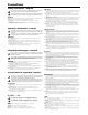
Quick Start — SW8/12 VGA Ars Step 1 Step 7 Step 2 a. Power off all devices. Connect one or two audio devices to the switcher’s audio output ports. Mount the switcher in a rack, or place it in the desired location. Wire the audio output connectors as shown below. Step 3 Do not tin the wires! Connect up to 8 (SW8) or 12 (SW12) video input cables. I Connect the sleeves to ground ( ). Connecting a sleeve to a negative (-) terminal will damage the audio output circuits.
Quick Start — SW8/12 VGA Ars, cont’d Step 9 Connect power cords and apply power in the following order: • Output devices (displays, projectors, monitors, audio devices, etc.) • SW8/12 VGA Ars switcher • Input devices (computers, audio devices, etc.) Step 10 Make the Normal/Auto Switch mode selection: • Normal — Hold Mode button and press Normal button. The Auto Switch LED is off. All input buttons function normally. • Auto switch — Hold Mode button and press Auto button. The Auto Switch LED is on.
Table of Contents Chapter One • Introduction . ..................................................................................................... 1-1 About This Manual ..................................................................................................................... 1-2 About the SW8/12 VGA Ars Switchers ........................................................................... 1-2 Features . ............................................................................................
Table of Contents, cont’d Appendix A • Specifications, Part Numbers, Accessories ................................. A-1 Specifications ............................................................................................................................... A-2 Part Numbers and Accessories .......................................................................................... A-4 SW8/12 VGA Ars switchers . ...............................................................................................
SW8/12 VGA Ars 1 Chapter One Introduction About This Manual About the SW8/12 VGA Ars Switchers Features
Introduction About This Manual This manual describes the function, installation, operation, and control of the SW8 VGA Ars and SW12 VGA Ars, 8- or 12-input, 2-output computer video (VGA) and audio switchers. About the SW8/12 VGA Ars Switchers The Extron SW8/12 VGA Ars switchers support audio video (A/V) systems that require 8 or 12 high resolution VGA-QXGA video and audio inputs to be switched to 1 or 2 outputs. Video and audio outputs are buffered.
Features SW8/12 VGA Ars switcher features include: • 8 or 12 video inputs with 15-pin HD connectors • 8 or 12 3.
Introduction, cont’d 1-4 SW8/12 VGA Ars • Introduction
SW8/12 VGA Ars 2 Chapter Two Installation and Operation Mounting the SW8/12 VGA Ars Switcher Rear Panel Cable Connections Front Panel Operating the SW8/12 VGA Ars Switchers
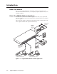
Installation and Operation Mounting the SW8/12 VGA Ars Switcher The SW8/12 VGA Ars can be placed on a desktop or easily mounted: • In a rack • Under a desktop • Through a desktop Desktop placement Affix the four included rubber feet to the bottom of the unit and place it in any convenient location. Rack mounting UL guidelines for rack mounting The following Underwriters Laboratories (UL) guidelines pertain to the installation of an SW8/12 VGA Ars switcher unit onto a rack. 2-2 1.
Mounting instructions Rack mounting requires the included MBD 149 1U, through-desk and rack mounting kit (part #70-077-03). Rack mount an SW8/12 VGA Ars unit as follows: 1. If present, remove the four rubber feet from the bottom of the unit. 2. Use four supplied 8-32 x 5/16” long screws to secure a mounting bracket to each side of the unit (figure 2-1). 3. Use four supplied 10-32 x 3/4” long screws to secure the bracket to the rail.
Installation and Operation, cont’d Mounting under a desktop Under-desk mounting requires the optional MBU 149 1U, under-desk mounting kit (part #70-222-01). Mount an SW8/12 VGA Ars under a desktop as follows: 1. Install the mounting brackets on the unit’s sides with the eight machine screws provided in the kit. 2. Hold the unit (with brackets attached) against the underside of the desk. Mark each bracket's hole location on the underside of the desk. 3. Drill 1/4" (6.
Mounting through a desktop Through desktop mounting requires the included MBD 149 1U, through-desk and rack mounting kit (part #70-077-03). Mount an SW8/12 VGA Ars unit through a desktop as follows: 1. If present, remove the four rubber feet from the bottom of the unit. 2. Cut an appropriately sized hole in the desktop. 3. Loosely install the mounting brackets on the unit’s sides with four machine screws provided in the kit. 4.
Installation and Operation, cont’d Rear Panel The SW8/12 VGA Ars switcher rear panel connectors are described below. 1 100-240V 2 50/60Hz I 3 4 1 N 3 5 O U T P U T S 7 P U 2 4 6 8 T S 5 6 7 SW8 VGA Ars 1 FIXED 2 L VARIABLE R L RS-232 R 1.2A MAX Figure 2-4 — SW8 VGA Ars rear panel 1 100-240V 2 50/60Hz I N 3 4 1 3 5 7 9 11 P U 2 4 6 8 T S 10 12 O U T P U T S 5 6 7 FIXED VARIABLE SW12 VGA Ars 1 2 L R L R RS-232 1.
Cable Connections Power connection When you are ready to apply power to your SW8/12 VGA Ars unit, connect the female end of the power cord to the AC outlet at the left edge of the rear panel, and connect the male end of the power cord to a 120/240 VAC power outlet. When power is applied all front panel LEDs light for one second, then go out. The LED for the previously selected input then comes on and remains lit until the current input is de-selected. 100-240V 50/60Hz I N 1 3 2 4 P U T S 1.
Installation and Operation, cont’d Audio input connections The switchers have 8 or 12 3.5mm female audio jacks adjacent to the corresponding computer video input port. Pin Name Connection 1 Tip left channel 2 Ring right channel 3.5mm Stereo Connector Tip (L+) Sleeve (Gnd) Ring (R+) Tip (L+) 3 Sleeve 100-240V 50/60Hz Sleeve (Gnd) signal ground I N 1 3 2 4 P U Audio input ports T S 1.
Audio output connections The switcher have two 3.5mm 5-pole captive screw audio output ports. The Fixed port delivers a fixed volume, stereo balanced/unbalanced audio output. The Variable port delivers a variable volume, stereo balanced/unbalanced audio output. The volume range is 0 (-84 dB) through 100 (0 dB). The default volume setting is 100 (0 dB). Volume is controllable only via the RS-232 port.
Installation and Operation, cont’d VSW I AAP connection The VSW I AAP (part #70-529-11, -21, -51) is an optional Architectural Adapter Plate that provides remote input connection and selection for some Extron switchers. The VSW I AAP can be connected to the SW8/12 VGA Ars input ports for input selection control. The VSW I AAP is equipped with a “Show Me” button for input selection, a female 15-pin HD VGA connector, and a 3.5 mm stereo audio jack.
6. Connect a VGA cable from an input device to the Computer input port on the VSW I AAP. 7. Apply power to the display device, the switcher, and then the input source. 8. Press the “Show Me” button on the VSW I AAP. The video input to the VSW I AAP is directed to the switcher’s output ports and should now be present on the display device. 9. If desired, connect an audio input to the VSW I AAP, and use the “Show Me“ button to test its output to the system’s audio output device.
Installation and Operation, cont’d IR 102 remote control connection The SW8/12 VGA Ars switcher can be controlled via its RS-232 port and an infrared signal. The IR 102 Remote Control Kit (part #70-224-01) is required. To connect an IR 102 Receiver to an SW8/12 VGA Ars switcher: 1. Connect a 9-pin serial cable, with only conductors 2, 3, and 5 connected, to the RS-232 output port on the IR 102 receiver. 2. Connect the serial cable to the RS-232 port on the switcher’s rear panel.
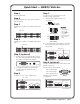
Front Panel The SW8/12 VGA Ars switcher front panel controls are described below. 1 AUTO SWITCH ACTIVE 2 1 2 3 MODE NORMAL AUTO 4 5 6 7 8 SW8 VGA Ars 3 4 5 Figure 2-17 — SW8 VGA Ars front panel 1 AUTO SWITCH 2 1 2 3 MODE NORMAL AUTO 4 5 6 7 8 9 10 11 12 ACTIVE SW 12 VGA Ars 3 4 5 Figure 2-18 — SW12 VGA Ars front panel Hold a b Auto switch active LED — Lights when the auto switch mode is enabled.
Installation and Operation, cont’d e Auto (Input 3) button — Hold Mode and press Auto to lock out the front panel input buttons and have the switcher select for output the highest number input with a sync signal present. If no sync signal is present, input #1 is selected by default.
SW8/12 VGA Ars 3 Chapter Three Control Remote control via Simple Instruction Set (SIS™) Updating Firmware
Control Remote Control via Simple Instruction Set (SIS™) The SW8/12 VGA Ars switchers can be controlled via RS-232 using Extron’s Simple Instruction Set (SIS™) commands. The RS-232 port communications protocols are: 9600 baud, 8 data bits, 1 stop bit, no parity, and no flow control. Cable pinouts are shown in the table below. Only pins 2, 3, and 5 are required. Disconnect all other conductors in the attachment cable for proper operation.
Error responses When the switcher receives a valid command, it executes the command and sends a response to the host device. If the unit is unable to execute the command because the command contains invalid parameters, it returns an error response to the host.
Control, cont’d Command/Response Table for SIS commands Command ASCII (Telnet) Response Additional description X!! InX!All] Select input X!video and audio. X!& X!$ InX!Vid] Select input X! video only. InX!Aud] Select input X! audio only. (host to switcher) (switcher to host) Input Selection Select video and audio Select video only Select audio only Auto Switch Normal switch mode 1# F1] Set switch mode to normal. Auto switch mode 2# F2] Set switch mode to auto.
Command ASCII (Telnet) (host to switcher) Response (switcher to host) Additional description View information, part number, and firmware requests Information request I/i Request part number N/n VX!•AX!•FX%•VmtX#•AmtX#] Current video/audio selection/ switch mode /mute status. x = part number 60-xxx-21] Query firmware revision Q/q y.yy] y.yy = firmware to two decimals EUpload} ...go ... Upl] “Upl” appears after the upload is complete.
Control, cont’d Updating Firmware Firmware updates for the SW8/12 VGA Ars are available on the Extron Web site. The Firmware Loader software is also available from the Extron site. Use the SIS “Q” command to determine the switcher’s current firmware level. Downloading the firmware To obtain the latest version of firmware for your SW8/12 VGA Ars switcher: 1. Visit the Extron Web site, click the Download tab, then click the Firmware link on the left sidebar menu.
4. Follow the instructions on the rest of the download screens to save the executable firmware file to your computer. Note the folder to which you save the file. 5. In the Windows Explorer or other file browser, locate the downloaded executable file, and double-click on it to open it. 6. Follow the instructions on the Installation Wizard screens to install the new firmware on your computer.
Control, cont’d Figure 3-5 — Extron firmware loader screen 7. Click OK. The firmware selection screen appears. 8. On the firmware selection screen, click Browse to open the Choose Firmware File window, and locate the firmware file that you downloaded. (By default, the firmware file is placed at c: Program Files\Extron\Firmware\SW when downloaded from the Extron Web site.) C The firmware file must have a .s19 extension. Uploading any other file type could cause the switcher to stop functioning.
9. On the Choose Firmware File window, double-click on the new firmware file to open it. The Choose Firmware File window closes, and the path to the selected firmware file is displayed in the “Select a firmware file” field on the firmware file selection screen. Figure 3-7 — Extron’s firmware loader screen 10. Click the Upload button. A status bar, which shows the progress of the upload, appears in the Firmware Loader window. The firmware upload to the switcher may take several minutes.
Control, cont’d 3-10 SW8/12 VGA Ars • Control
SW8/12 VGA Ars A Appendix A Specifications, Part Numbers, Accessories Specifications Part Numbers and Accessories
Specifications, Part Numbers, Accessories Specifications Video Gain.................................................. Unity Bandwidth....................................... 350 MHz (-3 dB) Crosstalk.......................................... -68 dB @ 10 MHz Video input Number/signal type...................... 8 or 12 (depending on the model) VGA-QXGA RGBHV, RGBS, RGsB, RsGsBs computer video, and HDTV component video Connectors......................................
Audio input Number/signal type...................... 8 or 12 (depending on the model) stereo, unbalanced Connectors...................................... 8 or 12 (depending on the model) 3.5 mm female stereo mini jacks; tip (L), ring (R), sleeve (Gnd) Impedance....................................... >10k ohms unbalanced, DC coupled Nominal level................................. -10 dBV (316 mV) Maximum level............................... +14 dBV, (unbalanced) at 1% THD+N N 0 dBu = 0.
Specifications, Part Numbers, Accessories, cont’d N All nominal levels are at ±10%. N Specifications are subject to change without notice. Part Numbers and Accessories SW8/12 VGA Ars switchers Model Part number SW8 VGA Ars 60-902-21 SW12 VGA Ars 60-946-21 Included parts Description Part number MBD 149 rack mount and through desk mounting kit 70-077-03 5-pole, 3.
Extron’s Warranty Extron Electronics warrants this product against defects in materials and workmanship for a period of three years from the date of purchase.
www.extron.com Extron Electronics, USA 1230 South Lewis Street Anaheim, CA 92805 800.633.9876 714.491.1500 FAX 714.491.1517 Extron Electronics, Europe Beeldschermweg 6C 3821 AH Amersfoort, The Netherlands +800.3987.6673 +31.33.453.4040 FAX +31.33.453.4050 Extron Electronics, Asia 135 Joo Seng Rd. #04-01 PM Industrial Bldg., Singapore 368363 +800.7339.8766 +65.6383.4400 FAX +65.6383.4664 © 2008 Extron Electronics. All rights reserved.