User’s Manual CAUTION Do not connect this device to a computer data or telecommunications network TP Receivers Family www.extron.com Extron Electronics, USA Extron Electronics, Europe Extron Electronics, Asia Extron Electronics, Japan 1230 South Lewis Street Anaheim, CA 92805 USA 714.491.1500 Fax 714.491.1517 Beeldschermweg 6C 3821 AH Amersfoort The Netherlands +31.33.453.4040 Fax +31.33.453.4050 135 Joo Seng Road, #04-01 PM Industrial Building Singapore 368363 +65.6383.4400 Fax +65.6383.
Precautions Safety Instructions • English This symbol is intended to alert the user of important operating and maintenance (servicing) instructions in the literature provided with the equipment. This symbol is intended to alert the user of the presence of uninsulated dangerous voltage within the product's enclosure that may present a risk of electric shock. Caution Read Instructions • Read and understand all safety and operating instructions before using the equipment.
Table of Contents Chapter 1 • Introduction .......................................................... 1-1 About the TP Receivers ....................................................... 1-2 Features ...................................................................................... 1-3 TP R BNC A receiver ............................................................... 1-3 TP R BNC AV receiver ............................................................. 1-4 TP R AV receiver ...............................
Table of Contents, cont’d Appendix • Specifications, Accessories, and Part Numbers ................................................................................... A-1 Specifications ......................................................................... A-2 Included Parts ......................................................................... A-5 Accessories ............................................................................... A-6 Cables /Adapters ..........................................
Introduction, cont’d Introduction It is possible to exceed the recommended distances, however, image quality may be reduced. About the TP Receivers The Extron Twisted Pair (TP) receivers receive transmissions of RGB video, component video, S-video, composite video, and stereo audio over Extron’s Skew-Free™ A/V UTP cable or standard Category (CAT) 5 unshielded twisted pair (UTP), shielded twisted pair (STP), or foil shielded twisted pair (FTP) cable.
Introduction, cont’d TP R BNC AV receiver TP R 15HD A receiver The TP R BNC AV receiver has the following features: The TP R 15HD A receiver has the following features: Video output — Provides RGBHV, RGBS, or RGsB video on 5 BNC connectors, and composite video on 1 BNC connector. Video output — Provides RGBHV, RGBS, and RGsB on a 15-pin HD connector. With an optional SY 15 HD-RGBHV cable, the receiver can output component video, S-video, or composite video.
Introduction, cont’d TP Receivers This page was intentionally left blank 2 Chapter Two Installation and Operation Installation Overview Front Panel Controls and Indicators Troubleshooting 1-6 TP Receivers • Introduction
Installation and Operation, Operation cont’d All TP transmitters include a 15V external power supply. The transmitters also receive power from the associated Extron TP receiver(s) (with the exception of the TP R 15HD A) via the TP cable. Extron recommends using the local power supply; however, the power supply may not be necessary in some applications.
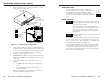
Installation and Operation, cont’d Remove the three screws on each side and the two screws on top of the cover (figure 2-1). Remove 8 Screws 1.
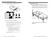
Installation and Operation, cont’d 1. Remove the three screws on each side and the one or two screws on top of the cover (figure 2-2). Remove (7) Screws Lift Cover straight up R WE DC PO.5A B A-V OU TP UT R V 15 TP R AV or TP R BNC AV Mounting the receiver Rack mounting (TP R BNC A, TP R BNC AV, TP R 15HD A) TP R BNC A, TP R BNC AV, or TP R 15HD AV — For optional rack mounting, mount the receiver on a 19" 1U Universal Rack Shelf (Extron part #60-190-01) (figure 2-3).
Installation and Operation, cont’d TP R 15HD A only — For optional rack mounting, mount the receiver on a VersaTools 19" 1U Rack Shelf (Extron part #60-190-20) (figure 2-4). The TP R 15HD A mounts in one of four locations on the rack.
Installation and Operation, cont’d For under-surface mounting, insert #8 wood screws into the four pilot holes. Tighten each screw into the mounting surface until just less than 1/4” of the screw protrudes. 6. For under-surface mounting, align the mounting screws with the slots in the brackets and place the receiver against the surface, with the screws through the bracket slots. 7.
Installation and Operation, cont’d 4 Computer video The TP R BNC A, TP R BNC AV and TP R 15HD A receive and output RGB video. These receivers can also receive component video, S-video, or composite video and output them on the R, G, and B signal lines. 3 10 5 15 5 SOG switch — Set this rear panel switch up for RGsB video and down for RGBHV or RGBS video. For RGBHV video, use the R, G, B, H/HV, and V BNCs. C Sync switch — Set this rear panel switch up for RGBS video and down for RGBHV or RGsB video.
Installation and Operation, cont’d Audio TP R BNC A and TP R AV — Wire the external 15V power supply into this 3-pole captive screw connector (figure 2-9) and plug the connector into the receiver. The power supply is included with the unit. All Extron TP receivers receive and output stereo audio. All receivers except the TP R 15HD A output the audio on both left and right RCA connectors and on 3.5 mm, 5-pole captive screw connectors. The TP R 15HD A outputs audio on the captive screw connector only.
Installation and Operation, cont’d Cable testing together; the signal transmitted on the shortest wire pair leads the other colors and appears to the left on the display. To ensure proper cable termination, each transmission cable system that uses CAT 5e should be tested (Extron’s Skew-Free UTP cable does not need to be tested). Testing the cable from the RJ-45 connections at the transmitter and receiver gives the most accurate indications of cable problems.
Installation and Operation, cont’d Front Panel Controls and Indicators 2 Manual/Auto switch (TP R BNC A and TP R BNC AV) — With this switch in the Auto position, the receiver automatically adjusts the level and peaking to compensate for long cable runs. In the Manual position, you can manually compensate for long cable runs using the level and peaking controls. 3 Auto LED (TP R BNC A and TP R BNC AV) — Indicates that the Manual/Auto switch is in the Auto position.
Installation and Operation, cont’d 10. For computer video from a laptop or for ungrounded AC distribution systems, the transmitter may need to be grounded. See Grounding the transmitter in the TP Transmitter Family User’s Manual, part #68-546-01. 11. Call the Extron S3 Sales & Technical Support Hotline if necessary. If the image is not displayed correctly 1. For computer/RGB video, if the output image looks too green, ensure that the receiver’s SOG switch is off. 2.
Specifications, Accessories, Specifications, Accessories, and and Part Part Numbers Numbers cont’d Video Number/signal type ................... 1 or 2 sets of proprietary analog signals Connectors .................................... 1 or 2 shielded RJ-45 female Video input — refer to the TP Transmitters Family User’s Manual, part #68-546-02 S/N ................................................ Crosstalk ....................................... Stereo channel separation .......... CMRR .....................
Specifications, Accessories, and Part Numbers cont’d TP R 15HD A .................... Yes, with optional VersaTools 1U rack shelf, part #60-190-20 or optional standard size 1U rack shelf, part #60-190-01. Also, projector mountable with optional mounting kit, part #70-212-01 or underfurniture mountable with optional mounting brackets, part #70-217-01. TP R BNC A, TP R BNC AV Yes, with optional 1U rack shelf, part #60-190-01.
Specifications, Accessories, and Part Numbers cont’d Skew-Free A/V cable, RJ-45 jacks Accessories Accessories Part number 150’ Skew-Free Plenum 26-570-09 26-570-10 P/S 150 Multiple output 15V power supply 60-432-01 200’ Skew-Free Plenum Extron 19" 1U Universal Rack Shelf 60-190-01 250’ Skew-Free Plenum 26-570-11 Extron 19" 1U Basic Rack Shelf 60-604-01 300’ Skew-Free Plenum 26-570-12 Extron VersaTools 19" 1U Universal Rack Shelf 60-190-20 CAT 6 Jack (various colors) 10-463-xx Extron Vers
Specifications, Accessories, and Part Numbers cont’d This page was intentionally left blank A-8 TP Receivers • Specifications, Accessories, and Part Numbers