User’s Manual TP T 15HD 45 and TP T A 45 Twisted Pair Video and Audio Transmitters www.extron.com Extron Electronics, USA Extron Electronics, Europe Extron Electronics, Asia Extron Electronics, Japan 1230 South Lewis Street Anaheim, CA 92805 USA 714.491.1500 Fax 714.491.1517 Beeldschermweg 6C 3821 AH Amersfoort The Netherlands +31.33.453.4040 Fax +31.33.453.4050 135 Joo Seng Road, #04-01 PM Industrial Building Singapore 368363 +65.6383.4400 Fax +65.6383.
Precautions Safety Instructions • English This symbol is intended to alert the user of important operating and maintenance (servicing) instructions in the literature provided with the equipment. This symbol is intended to alert the user of the presence of uninsulated dangerous voltage within the product's enclosure that may present a risk of electric shock. Caution Read Instructions • Read and understand all safety and operating instructions before using the equipment.
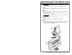
Quick Start Guide — TP T 15HD 45 / A 45 CAUTION Installation and service must be performed by authorized personnel only. These units must be installed in accordance with national and local electrical codes. Step 1 Power off all devices and disconnect them from the power source. Step 2 Connect the UTP cable from the receiver to the 8-pin connector on the TP T 15HD 45. To wire the connector, see Rear Panel Connectors in chapter 2 for the pinout table.
Quick Start Guide — TP T 15HD/A 45, cont’d Table of Contents Step 5 Chapter 1 • Introduction .......................................................... 1-1 If the TP T A 45 is being installed, connect the TP T A 45 to the TP T 15HD 45. See Rear Panel Connectors in chapter 2. The TP T 15HD 45 may be used as a stand-alone video module only without the TP T A 45. The TP T A 45 derives its power from the TP T 15HD 45.
Table of Contents, cont’d TP T 15HD 45 and TP T A 45 1 Chapter One Introduction Features ii TP T 15HD 45 and TP T A 45 • Table of Contents
Introduction, cont’d Introduction The Extron TP T 15HD 45 twisted pair transmitter and the matching TP T A 45 audio input module provide a system for sending RGBHV, RGBS, RGsB, component, composite, or S-video and stereo audio signals over Extron Skew-Free™ A/V UTP cable or CAT 5/5e/6 UTP cable to a compatible TP or VTR receiver. An external 12 VDC power supply provides power to both the TP T 15HD 45 and the TP T A 45. The TP T A 45 inputs unbalanced audio through a 3.
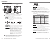
Installation, cont’d Installation AUDIO AUDIO 1b OUTPUT 1 2 3 4 5 6 7 8 12 VDC .5A MAX. 4 2 AUDIO AUDIO The wire gauge should be 14 -22 AWG and the maximum distance between the modules should not exceed 25 feet. 12 VDC .5A MAX. 3 2 Power input captive screw connector — Connect the included 12 VDC external power supply to the 2-pole female direct insertion captive screw connector.
Installation, cont’d Front Panel Connectors and Indicators 12345678 TP T 15HD 45 TP T A 45 1 1 COMPUTER 1&2 7&8 3 2 3&6 4&5 Twisted Wire Pairs AUDIO INPUT INPUT 3 Power input captive screw connector — Connect power input cables to the 2-pole female direct insertion captive screw connector. Figure 2-2 — Front panel views + Power Input Captive Screw Direct Insertion Connector Power LED indicator — The LED lights green whenever power is applied.
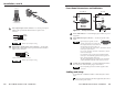
Installation, cont’d 2 Connect the TP T 15HD 45 and its receiver to either end of the UTP cable. See Cable testing and Skew delay problems in this chapter. For best results, use Extron Skew-Free™ A/V UTP cable available in bulk or in various preterminated lengths. If necessary, regular CAT 5, CAT 5e, and CAT 6 cable may be used. 3 Connect the external power supply to the TP T 15HD 45 and TP T A 45 (if installed). See Rear Panel Connectors in this chapter.
Installation, cont’d Skew delay problems CAT 5 TP cable can lead to registration errors between the red, green, and blue video signals. Pair skew can be measured with test equipment or identified by viewing a crosshatch test pattern with a critical eye to determine if either the red, green, or blue video image leads (appears to the left of) the other two video images. These images can be minimized or eliminated by one of the following methods: • Switch to Extron’s Enhanced Skew-Free A/V UTP cable.
Reference Information, cont’d Reference Information Specifications Video — video models Number/signal type ................... 1 set of proprietary analog signals Connectors TP T 15HD 45 .................... (1) 8-pin spring force captive wire connector Video input — video models Number/signal type TP T 15HD 45 ....................
Reference Information, cont’d All models ......................... 3 lbs (2 kg) Vibration ....................................... ISTA 1A in carton (International Safe Transit Association) Compliances ................................. CE, FCC Class A, VCCI, AS/NZS, ICES MTBF ............................................. 30,000 hours Warranty ....................................... 3 years parts and labor Parts Lists Included parts Description Power supply: universal 12 VDC, 1.
Reference Information, cont’d TP T 15HD 45 and TP T A 45 • Reference Information