User’s Manual RGB 130xi , 134xi , 150xi Universal Interfaces 68-410-02 Printed in the USA
Precautions Safety Instructions • English This symbol is intended to alert the user of important operating and maintenance (servicing) instructions in the literature provided with the equipment. This symbol is intended to alert the user of the presence of uninsulated dangerous voltage within the product's enclosure that may present a risk of electric shock. Caution Read Instructions • Read and understand all safety and operating instructions before using the equipment.
Table of Contents Chapter 1 • Introduction ......................................................... 1-1 About this Manual ................................................................ 1-1 About the Interfaces ............................................................ 1-1 Features ...................................................................................... 1-1 Chapter 2 • Controls and Installation ........................ 2-1 Front and Rear Panels ........................................
xi , 134xi xi , 150xi xi Table of Contents RGB 130xi
xi , 134xi xi , 150xi xi RGB 130xi 1 Chapter One Introduction About this Manual About the Interfaces Features xi , 134xi xi , 150xi xi Table of Contents RGB 130xi
Introduction About this Manual This manual documents three universal interfaces: RGB 130xi, RGB 134xi, and RGB 150xi. Unless otherwise specified, any references to “the interface” shall refer to the features or operation of all three interfaces. About the Interfaces The RGB 130xi, 134xi, and 150xi are universal interfaces with a video bandwidth of 300 MHz and a horizontal frequency range of 15-150 kHz. Features 2-color power/signal LED — When the interface is On, the power/signal LED will light amber.
xi , 134xi xi , 150xi xi RGB 130xi 2 Chapter Two Controls and Installation Front and Rear Panels Installation xi , 134xi xi , 150xi xi Introduction RGB 130xi
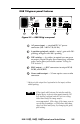
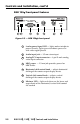
Controls and Installation Front and Rear Panels xi front panel features RGB 150xi AUDIO ANALOG ID PIN 4 ID PIN 11 RGB 150 INPUTS BUFFERED LOCAL MONITOR OUTPUT UNIVERSAL INTERFACE W/ADSP MIN/MAX H. SHIFT 1 2 3 4 5 6 7 Figure 2-1 — RGB 150xi front panel 2-1 1 2-color power/signal LED — lights amber to indicate power On only; lights green to indicate power On with video signal present 2 Audio input jack — 3.
RGB 150xi xi rear panel features 0.5A MAX.
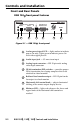
Controls and Installation, cont’d RGB 130xi xi front panel features RGB 130 UNIVERSAL INTERFACE W/ADSP INPUTS AUDIO ANALOG/ECL MBC MIN/MAX H. SHIFT V. SHIFT POWER 1 2 3 4 5 6 7 Figure 2-3 — RGB 130xi front panel 2-3 1 2-color power/signal LED — lights amber to indicate power On only; lights green to indicate power On with video signal present 2 Audio input jack — 3.5 mm stereo input 3 Analog/ECL input connector — 9-pin D male analog video input connector 4 MBC power — 2.
RGB 130xi xi rear panel features 0.5A MAX.
Controls and Installation, cont’d RGB 134xi xi front panel features RGB 134 UNIVERSAL INTERFACE W/ADSP INPUTS AUDIO ANALOG/ECL MBC MIN/MAX H. SHIFT V. SHIFT 5 6 POWER 1 2 3 4 7 Figure 2-5 — RGB 134xi front panel 2-5 1 2-color power/signal LED — lights amber to indicate power On only; lights green to indicate power On with video signal present 2 Audio input jack — 3.5 mm stereo input 3 Analog/ECL input connector — 9-pin D male analog video input connector 4 MBC power — 2.
RGB 134xi xi rear panel features 0.5A MAX.
Controls and Installation, cont’d Installation Easy setup procedure Except where noted, the installation procedures for the RGB 130xi, 134xi, and 150xi are the same. See “Cabling” in this chapter for more information. 1 If desired, mount the interface to a desk or other suitable surface using Extron’s optional mounting kit. See “Mounting the interface” in the next section. 2 Turn off power to the computer or workstation and its monitor. Turn off power to the projector or display device.
Mounting the interface To mount the interface under a desk or in a podium, do the following: 1. Attach the mounting brackets to the interface using six machine screws supplied with the mounting kit (see figure 2-7). INP UT BU MOFFER NIT ED OR LO OU CA TP L UT H. SH IFT MA C INT RG FA CE B 103 xi W /AD SP ER Figure 2-7 — Attaching the under desk brackets 2.
Controls and Installation, cont’d To mount the interface through a desk or table, do the following: 1. Attach the mounting brackets to the interface using four machine screws and washers (supplied with the mounting kit), as indicated in figure 2-9. U T IN P B M UFF O E N R IT E O D R LO O U C TP A U L T T H IF H .S M A C R FA R C GB E W 10 /A 3 xi D S P IN TE Figure 2-9 — Attaching the through desk brackets 2.
Cabling Each interface can connect to the computer or workstation’s local monitor and to a projector or other display device. The diagrams below show how to connect each of the interfaces. Connect the computer to the interface’s Analog/ECL connector. Front AU DI O INP UT MB PO C WE UN IVE R H. RS AL SH IFT INT Rear RG FA CE B 130 xi W /AD SP MIN /MA X ER H. SH IFT SOG OUT DDSP SERR SPARE 1. 0.5A V MBC Buffer or MBC/LBC Cable UT TP OU EL/ LEV K PEA 50% -240 100 0.
Controls and Installation, cont’d AU DI O INP UT ID PIN 4 ID PIN 11 Front UN IVE RS AL INT Rear RG FA CE B 150 xi W /AD SP MIN /MA X ER H. SH IFT SOG OUT DDSP SERR SPARE UT 0.5A V TP OU EL/ LEV K PEA 50% -240 100 0.8V TY UNI % 100 0.9V 0 Hz 50/6 Audio Power or PC Computer Monitor Projector Figure 2-13 — RGB 150xi xi installation 2. Connect the interface cable marked “Video input” to the computer’s video output (where the monitor was originally connected). 3.
Connecting audio output Before connecting audio, determine whether your audio system is unbalanced or balanced. Then, follow the instructions below to connect unbalanced audio, or the instructions for “Balanced audio” to connect balanced audio. Wiring the audio incorrectly may damage the audio output circuits. Unbalanced audio To attach the interface to an unbalanced audio system, do the following: 1. Attach the audio cable to an unbalanced powered speaker input connector (tip and sleeve), as shown here.
Controls and Installation, cont’d 3. Slide the audio cable connector into the audio output connector on the interface. Balanced audio To attach the interface to a balanced audio system, do the following: 1. Attach the audio cable to a balanced speaker input connector (tip, ring, and sleeve). Tip (+) Sleeve Ring (-) Tip (+) Sleeve 2. Attach the audio cable to the audio cable connector (Extron part number 10-319-10). Fasten the captive screws inside the audio cable connector as shown in figure 2-14.
Setting the DIP switches DIP switches can be found on the front panel of the RGB 150xi and on the rear panels of the RGB 150xi, 130xi, and 134xi. The switches may be either the rocking type or the sliding type. 1 2 3 4 1 2 3 4 To set the rocking-type DIP switches, use a small screwdriver to depress the appropriate end of each switch. ID PIN 4 ID PIN 11 To set the sliding-type DIP switches. use a small screwdriver to slide the switch to the on/closed or off/open position.
Controls and Installation, cont’d devices, such as LCD (liquid crystal display), DLP (digital lamp processing) and plasma displays. OFF — If this switch is set to Off, the interface performs sync processing operations, such as horizontal shift, using Extron’s ADSP™. Turning on the DDSP feature disables the horizontal shift control.
Setting internal jumpers The jumpers inside the interface(s) are set at the factory for optimal use by most systems. However, you can change a jumper setting to meet the needs of a particular system. The user-configurable, internal jumpers control the following functions: • horizontal and vertical sync polarity • vertical sync pulse width. Follow these steps to change the jumper settings. The RGB 134xi is shown for illustration, but the steps apply to all interfaces. 1.
Controls and Installation, cont’d pins 1 and 2 connected: 1 and 2 pins 2 and 3 connected: 2 and 3 Rear 1 J19 1 J20 1 J20: Sync polarity jumper J40 J40: Vertical sync width jumper Power Supply Front Figure 2-16 — Circuit board jumper locations 4. Configure the jumpers. To configure the jumpers, use pliers to pull the jumper shunt off the pins, then place the jumper on the appropriate pins.
The jumpers perform the following functions: Negative J20: Sync polarity jumper — This jumper adjusts the output sync polarity. Horizontal (H) and vertical Follow (V) sync output can either follow input sync polarity, or be forced to negative. • If the jumper is placed on pins 1 and 2, output H and V sync polarities will be forced to negative.
2-19 xi , 134xi xi , 150xi xi Controls and Installation RGB 130xi
xi , 134xi xi , 150xi xi RGB 130xi A Appendix Specifications Accessories and Part Numbers Mounting Templates xi , 134xi xi , 150xi xi Operation RGB 130xi
Appendix Specifications — RGB 130xi, 134xi, 150xi Video input Number/type .............................. 1 analog RGBHV, RGBS, RGsB, RsGsBs Connectors .................................... 1 15-pin HD male (150xi) 1 9-pin D male (130xi and 134xi) Nominal level(s) .......................... Analog — 0.3V to 1.5V p-p Maximum level(s) ....................... Analog — 1.5V p-p Impedance ....................................
Max. rise/fall time ...................... 3.5 nS Polarity .......................................... RGBHV: when RGBHV is input,polarity follows input; otherwise negative RGBS, RGsB: ............................ negative Audio input Number/type .............................. 1 PC level stereo, unbalanced Connectors .................................... 1 3.5 mm stereo jack, 2 channel; tip (L), ring (R), sleeve (ground) Impedance .................................... 10 kohms, DC coupled Minimum level ......
Appendix, cont’d Enclosure type ............................. Metal Enclosure dimensions of 130xi and 150xi ........................................................ 1.70" H x 6.35" W x 6.00" D 4.32 cm H x 16.13 cm W x 15.24 cm D Enclosure dimensions of 134xi ........................................................ 1.68" H x 8.70" W x 6.00" D 4.26 cm H x 22.09 cm W x 15.24 cm D Shipping weight .......................... 6 lbs (2.7 kg) Vibration .......................................
Accessories and Part Numbers Thunder™ Mounting Kits Under desk mounting kit .................. Through desk mounting kit .............. 70-077-01 70-077-02 xi and RGB 134xi xi Monitor breakout cables: RGB 130xi MBC VGA/XGA HR .......................... MBC Mac/Quadra .............................. MBC SUN Sparc HR ........................... MBC SGI/13W3 HR ............................
Appendix, cont’d BNC cables BNC-5 BNC-5 BNC-5 BNC-5 BNC-5 BNC-5 BNC-5 BNC-5 BNC-5 BNC-5 BNC-5 BNC-5 BNC-5 BNC-5 3’ HR ........................................ 6’ HR ........................................ 12’ HR ...................................... 25’ HR ...................................... 50’ HR ...................................... 75’ HR ...................................... 100’ HR .................................... 3’ HRP ..................................... 6’ HRP ........................
xi , 134xi xi , 150xi xi Appendix RGB 130xi A-6
A-7 xi, 134xi xi, 150xi xi Appendix RGB 130xi
xi , 134xi xi , 150xi xi Appendix RGB 130xi A-8
A-9 xi, 134xi xi, 150xi xi Appendix RGB 130xi
FCC Class A Notice Note: This equipment has been tested and found to comply with the limits for a Class A digital device, pursuant to part 15 of the FCC Rules. These limits are designed to provide reasonable protection against harmful interference when the equipment is operated in a commercial environment. This equipment generates, uses and can radiate radio frequency energy and, if not installed and used in accordance with the instruction manual, may cause harmful interference to radio communications.
EXTRON ELECTRONICS/RGB SYSTEMS, INC. 1230 South Lewis Street, Anaheim, CA 92805 800.633.9876 714.491.1500 FAX 714.491.1517 USA EXTRON ELECTRONICS, EUROPE Beeldschermweg 6C, 3821 AH Amersfoort +31.33.453.4040 FAX +31.33.453.4050 The Netherlands EXTRON ELECTRONICS, ASIA 41B Kreta Ayer Road, Singapore 089003 +65.226.0015 FAX +65.226.0019 Singapore EXTRON ELECTRONIC INFORMATION EXTRONWEB™: www.extron.com EXTRONFAX™: 714.491.