
User Guide


Installation and Operation, cont’d
USP 405 • Installation and Operation2-6
15
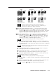
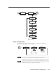
RGB or HDTV component output — Connect coaxial cables from these
female BNC connectors to an RGB output device or to an HDTV component
video device. Connect cables for the appropriate signal type, as shown
here.
R
/R-Y
G
/Y
B
/B-Y
HVS
R
/R-Y
G
/Y
B
/B-Y
HVS
R
/R-Y
G
/Y
B
/B-Y
HVS
R
/R-Y
G
/Y
B
/B-Y
HVS
RGBHV RGBS
RGsB HDTV Component Video
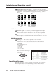
Genlock connections
16
Genlock output — Connect any downstream equipment that requires
genlocking to this female BNC connector to route the black burst signal
throughout the system in broadcast or other sync-critical applications.
17
Genlock input — Connect an external black burst signal to this female
BNC connector for genlocking the video signal in broadcast or other sync-
critical applications.
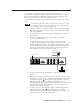
RS-232 connection
18
RS-232 port — This connector provides for two-way RS-232
communication. See the chapter 3, “Serial Communication”, for
information on how to install and use the control software and SIS
commands.
The default protocol is
• 9600 baud
• 1 stop bit
• no parity
• no flow control.
The rear panel RS-232, 9-pin D
connector has the following pin
assignments:
DB9 Pin Locations
Female
51
96
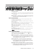
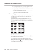
Front Panel Features
The front panel buttons, controls, and LCD of the USP 405, are shown below.
The front panel buttons can be labeled using the Button-Label Generator
software that is described in chapter 3, “Serial Communication”.
Pin RS-232 function Description
Contact closure
Input 1
1
Transmit data
Tx
2
No connection
–
9
Contact closure
Input 5
8
Contact closure
Input 4
7
Contact closure
Input 3
6
Signal ground
Gnd
5
Contact closure
Input 2
4
Receive data
Rx
3