
User Guide

Extron • VS 200 SL • User’s ManualExtron • VS 200 SL • User’s Manual
IN OUT
IN OUT
IN OUT
IN OUT
ShiftLock Operation
2-2
IN OUT
ShiftLock
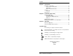
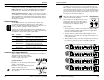
The ShiftLock feature allows two or more VS 200 SL units to be
linked together so that all the units shift together. A toggle switch
on the front panel allows one unit to be set as the master. Each of
any other units connected must be set as a slave. The shift signal
goes from the master to all slaves. The ShiftLock controls on the
front panel are described in chapter 3.
_ When the switch is set to Slave, the VideoShift
controls for that unit are disabled.
Two connectors on the back panel are for the
master-slave interconnecting cables. Extron
provides the cable connectors. See page 2-3
for instructions on making the cables.
Setup example:
1. The master unit has a cable connected from its ShiftLock Out
port to the ShiftLock In port of the first slave. Its toggle switch
must be set to the Master position.
2. The first slave has a cable from its ShiftLock Out port to the
ShiftLock In port of the next slave. Its toggle switch must be set
to the Slave position.
3. Repeat step #2 for each slave unit, except that the last slave (or
the only slave), will have no cable in its ShiftLock Out port.
Operation
2-1
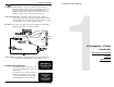
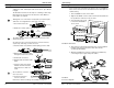
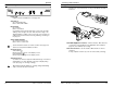
Rear Panel Operation
Following is the operation of VS 200 SL switches and connectors.
BNC Connectors – Connect Hi-Res BNC cables per application
requirements. See "Automatic Sync Output Detection" below.
ShiftLock In/Out Connectors – Allows connection of more than
one VS 200 SL to synchronize shifting. Use 2-conductor cables to
daisy-chain ShiftLock control between master and slave devices.
Set up ShiftLock only on the master; slaves shift with the master.
See pages 2-2 and 2-3.
DIP Switch Settings
The VS 200 SL has auto sync, which means it outputs sync
according to the impedance detected on the output cables.
However, the DIP switch settings take priority. If a switch is set, it
forces a condition, regardless of what is detected.
Following are the DIP switch settings for the VS 200 SL. In the
default positions (all switches OFF), sync output is determined by
the impedance detected through the output cables.
Sw# Position Function
1 ON Always separate H and V sync
OFF-normal Automatic sync output detection
2 ON Always negative sync
OFF-normal Sync output polarity follows Input
3 ON No serration pulses
OFF-normal Serration pulses pass through.
(or added if not already present)
4 ON Vertical sync width = 2-3 times normal
OFF-normal Vertical sync width = normal
5 Not used
Automatic Sync Output Detection
Sync is output in one of two ways, depending on the impedance
detected through the output cables:
Impedance = 75 ohm on R, G, and B,
or up to 1 kohm on sync lines.
Cabling Examples:
• Impedance on only R, G, B, & H/HV channels,
output = composite sync.
• Impedance on R, G, B, H/HV & V channels
output = separate H & V sync.
__ Turning a DIP switch ON overrides automatic
sync detection.