User’s Manual VSC 75 Video Scan Converter Extron Electronics, USA 1230 South Lewis Street, Anaheim, CA 92805 800.633.9876 714.491.1500 FAX 714.491.1517 USA Extron Electronics, Europe Beeldschermweg 6C, 3821 AH Amersfoort +31.33.453.4040 FAX +31.33.453.4050 The Netherlands Extron Electronics, Asia 135 Joo Seng Rd. #04-01, PM Industrial Bldg. +65.383.4400 FAX +65.383.4664 Singapore 368363 Extron Electronics Information ExtronWEB™: www.extron.com ExtronFAX™: 714.491.
Precautions Safety Instructions • English This symbol is intended to alert the user of important operating and maintenance (servicing) instructions in the literature provided with the equipment. This symbol is intended to alert the user of the presence of uninsulated dangerous voltage within the product's enclosure that may present a risk of electric shock. Caution Read Instructions • Read and understand all safety and operating instructions before using the equipment.
Table of Contents Chapter 1 • Introduction .......................................................... 1-1 About the VSC 75 ................................................................... 1-2 Features ...................................................................................... 1-2 Chapter 2 • Installation and Operation ......................... 2-1 Installation Overview .......................................................... 2-2 Mounting the VSC 75 ..........................................
Table of Contents, cont’d VSC 75 1 Chapter One Introduction About the VSC 75 Features ii VSC 75 Table of Contents
Introduction, cont’d Introduction About the VSC 75 Extron’s VSC 75 is a high resolution computer-to-video scan converter with all-digital controls. The VSC 75 converts a computer video signal into two display outputs — composite video and S-video — for simultaneous scanconverted output on two separate devices. This allows the video from a computer to be displayed on a television monitor or recorded on a DVD, VCR, video editing bay or other recording device. All of the outputs are NTSC/PAL.
Introduction, cont’d VSC 75 2 Chapter Two Installation and Operation Installation Overview Mounting the VSC 75 Front Panel Features Rear Panel Features Cabling Optimizing the Image Troubleshooting 1-4 VSC 75 Introduction
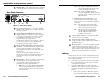
Installation and Operation, cont’d Installation and Operation screws from the underside of the shelf, and securely fasten them into diagonally-opposite corners as shown in figure 2. Installation Overview To install and set up the VSC 75, follow these basic steps: 1 Turn all of the equipment off. Make sure that the source computer, the VSC 75, and the output devices (projector, monitors) are turned off and disconnected from the power source. 2 Mount the scan converter.
Installation and Operation, cont’d Front Panel Features controls. Adjustments can still be made via RS-232 control when executive mode is active. CENTERING/PAN SIZE FLICKER FILTER 3 I MIN/ MAX II FREEZE TEST SIZE VSC 75 SCAN CONVERTER 1 2 3 4 5 6 7 8 This LED lights to indicate that the test feature is active. Figure 3 — VSC 75 front panel Adjustments to front panel features and controls do not affect the local monitor. 1 2 Power/signal lock LED — If this indicator...
Installation and Operation, cont’d 8 ON — The output is in PAL (Phase Alternate Line) format (625 lines/frame at 50 Hz vertical, 15.625 kHz horizontal). OFF — The output is in NTSC (National Television Standards Committee) format (525 lines/frame at 60 Hz vertical, 15.734 kHz horizontal). Min/Max LED — This lights red when the minimum or maximum limit of a control (6) has been reached. Rear Panel Features 0.
Installation and Operation, cont’d the other (15-pin D) end into the computer’s video output connector. VSC 75 Rear Panel 0.3A MAC • If the source computer is a VGA-type PC, plug the Mac (15-pin D) end into the VSC 75, and plug the other (15-pin HD) end into the computer’s video output connector. 50/60 Hz I N P U T S PAL OUT 75 OHM 100-240 V OUTPUTS VIDEO S-VIDEO VGA RS-232 RS-232 Control or MAC 50/60 Hz I N P U T S VGA or 0.3A MAC 50/60 Hz I N P U T S PAL OUT 75 OHM 100-240 V 0.
Installation and Operation, cont’d VGA Pin Function Mac Pin 1 2 3 4 5 6 7 8 9 10 11 12 13 14 15 Red video Green video Blue video ID bit ID bit Red ground Green ground Blue ground Not used Composite & vertical sync gnd ID bit ID bit Horizontal sync Vertical sync ID bit/composite sync 2 5 9 4 8 1 6 13 — 11, 14 7 10 15 12 3 3. Press the Size button again to turn the size feature off. 4. Center the picture by rotating the horizontal and vertical Centering/Pan/Size rotary controls. 5.
Installation and Operation, cont’d If the image is not displayed correctly Symptoms Solutions The picture is shifted off the screen edges. Adjust the centering and sizing controls ( , ). The image is stable, but it has ghosting or blooming. Change the 75 ohm/high Z video input termination. If that doesn’t solve the problem, use a different input cable. The picture is faint or cuts out, and the signal is weak. Video input may be double-terminated.
RemoteCommunication Control, cont’d Serial The VSC 75 can be controlled by a host computer or other control device via an RS-232 connection with a protocol of 9600 baud, 1 stop bit, no parity, and no flow control. The control device (host) can use either Extron’s Simple Instruction Set (SIS) or the graphical control program for Windows.
X1 VSC 75 Serial Communication X2 = Vertical filtering level (1 through 2) = 1 = On, 0 = Off Command/response table Command description Command ASCII Hex Response to host Additional description Horizontal shift Shift right one step Shift left one step {H }H 7B + 48 7D + 48 Hph + Hph - Increment up Increment down {/ }/ 7B + 2F 7D + 2F Vph + Vph - Increment up Increment down {: }: 7B + 3A 7D + 3A Hsz + Hsz - Increment up Increment down {; }; 7B + 3B 7D + 3B Vsz + Vsz - Increment up Inc
Remote Control, cont’d Control Software for Windows The included graphical control software for Windows offers another way to control the VSC 75 via RS-232 connection in addition to the Simple Instruction Set commands listed on pages 3-4 to 3-5. The control software is compatible with Windows 3.1/3.11, Windows 95/98 and Windows NT. The VSC 75 uses version 3.2 or higher of Extron’s VSC and DDS Control Program, which is included with the VSC 75.
Remote Control, cont’d VSC 75 A Appendix Specifications Part Numbers and Accessories Specifications Included Parts Accessories 3-8 VSC 75 Serial Communication
Specifications, cont’d Specifications Video input Control/remote — scan converter Number/signal type ................... 1 VGA, 1 Mac analog RGBHV, RGBS, RGsB Connectors .................................... VGA ........................... 15-pin HD female Mac ............................ 15-pin D female Nominal level(s) .......................... Analog — 1V p-p Minimum/maximum level(s) .... Analog — 0V to 2V p-p with no offset Impedance ....................................
Accessories and Part Numbers, cont’d Accessories and Part Numbers Included Parts These items are included in each order for a VSC 75: Included parts Part number VSC 75 60-321-01 Mac-HV/VGA cable (6 feet) 26-462-01 S-video cable (6 feet) 26-316-02 VSC 75 user’s manual 68-483-01 VSC/DDS control software for Windows version 3.