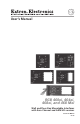
User’s Manual RGB 460xi, 464xi, 468xi, and 468 Mxi Wall and Floor Box Mountable Interfaces with Euro Channel and AKM UK versions 68-542-01 Rev.
Precautions Safety Instructions • English This symbol is intended to alert the user of important operating and maintenance (servicing) instructions in the literature provided with the equipment. This symbol is intended to alert the user of the presence of uninsulated dangerous voltage within the product’s enclosure that may present a risk of electric shock. Caution Read Instructions • Read and understand all safety and operating instructions before using the equipment.
Precautions 安全须知 • 中文 警告 这个符号提示用户该设备用户手册中 有重要的操作和维护说明。 电源 • 该 设 备 只 能 使 用 产 品 上 标 明 的 电 源 。 设 备 必须使用有地线的供电系统供电。 第三条线 (地线)是安全设施,不能不用或跳过。 这个符号警告用户该设备机壳内有暴 拔掉电源 • 为安全地从设备拔掉电源,请拔掉所有设备后 或桌面电源的电源线,或任何接到市电系统的电源线。 露的危险电压,有触电危险。 电源线保护 • 妥善布线, 避免被踩踏,或重物挤压。 注意 阅读说明书 • 用 户 使 用 该 设 备 前 必 须 阅 读 并 理 解所有安全和使用说明。 保存说明书 • 用户应保存安全说明书以备将来使 用。 遵守警告 • 用户应遵守产品和用户指南上的所有安 全和操作说明。 维护 • 所有维修必须由认证的维修人员进行。 设备内部 没有用户可以更换的零件。为避免出现触电危险不要自 己试图打开设备盖子维修该设备。 通风孔 • 有些设备机壳上有通风槽或孔,它们是用来防止 机内敏感元件过热。 不要用任何东西挡住通风孔。 锂电池 • 不正确的更换电池会有爆炸的危险。 必
Table of Contents Table of Contents Chapter One • Introduction ......................................... 1-1 About this Manual.................................................. 1-2 About the RGB 460xi Series................................... 1-2 Features................................................................... 1-3 Chapter Two • Installation and Operation ................. 2-1 Installation Overview............................................. 2-2 UL Guidelines. ..................................
Table of Contents, cont’d ii RGB 460xi Series • Table of Contents
RGB 460xi Series 1 Chapter One Introduction About this Manual About the RGB 460xi Series Features
Introduction About this Manual This manual describes the Extron RGB 460xi Series of universal wall, furniture, and floor box mountable interfaces and explains how to configure and operate them. Unless otherwise noted, the term “RGB 460xi” or “interface” is used throughout this manual to refer collectively to all models in the RGB 460xi Series. Detailed mounting instructions are available in other Extron publications: • For wall box installations, refer to one of the available wall box installation guides.
Features Horizontal shifting control — The displayed image may be shifted to the left or right by turning a front panel knob. Advanced Digital Sync Processing™ (ADSP™) — ADSP allows sync processing operations, such as horizontal centering, to occur without affecting the sync timing of the signal. This allows horizontal centering to be applied to signals that are output to digital display devices such as LCD projectors, DLP projectors and plasma displays.
Introduction, cont’d 1-4 RGB 460xi Series • Introduction
RGB 460xi Series 2 Chapter Two Installation and Operation Installation Overview Front Panel Features and Cabling Rear Panel Features and Cabling Euro Channel and Floor Box Versions Adapter Plate (AAP/MAAP) Mounting Pre-installation Testing Interface Mounting Application Examples
Installation and Operation Installation Overview C Installation and service should be performed by authorized personnel only. UL Listed electrical boxes are recommended. See “UL guidelines” in this chapter. To install and set up an RGB 460xi Series interface, follow these steps: 1 Turn off all equipment. Disconnect the computer, the interface, and the output devices (e.g., projector/monitor, speakers, etc.) from the power source.
Front Panel Features and Cabling 6 C Do not remove the faceplate screws (a) while the interface is attached or the detached interface may fall down inside the wall or mounting. RGB 460xi 1 1 H. SHIFT MONITOR 7 2 INPUT MIN/MAX 8 NO MONITOR 3 MONITOR AUDIO 1 6 1 7 RGB 464xi 9 1 10 RGB 460xi 4 5 1 H.
Installation and Operation, cont’d a Faceplate screws — These screws secure the faceplate to the rest of the interface. C b Power/signal LED — This LED lights Audio Plugs.eps • Yellow to indicate the interface is receiving power. • Green to indicate that an active sync signal is present at the input and the interface is receiving power. N c Do not remove these faceplate screws while the interface is attached to the wall or the detached interface may fall down inside the wall.
i Composite video connector (RGB 464xi) — This female RCA-to-BNC type connector provides pass-through capability for composite video input. j S-video pass-through connector (RGB 464xi) Connect an Audio— Plugs.eps S-video source to this 4-pin mini DIN pass-through connector. kl RCA audio connectors (RGB 464xi) — Connect the left audio signal cable to the white RCA connector (k L/Mono), and the right audio signal cable to the red RCA connector (l R) for unbalanced stereo audio pass-through input.
Installation and Operation, cont’d Blank plates (two single space and one double space) are included with the interfaces to cover unused spaces. Adapter plates must be ordered separately (see “AAP/MAAP Availability” in appendix A). They must also be attached to the faceplate and cabled before the interface is installed in the wall or furniture. The screws needed for installing the adapter plates are supplied (MAAPs), or built into the plates (AAPs), so no additional screws are needed. 1.
a DIP switches — This bank of DIP switches, as illustrated below, controls sync on green output, composite sync output, DDSP (Digital Display Sync Processing), serration pulse output, vertical sync pulse width, and composite sync routing. Moving a switch up sets it "On" and moving it down sets it "Off". Closed / On 1 2 3 4 5 6 7 8 Open / Off N The default for all DIP switches, except for switch 7, is Off (down).
Installation and Operation, cont’d 5 — Vertical sync pulse width — Try adjusting the output vertical sync pulse width if no picture appears, the picture cuts in and out, or the picture is scrambled. Off — The vertical sync pulse is wide. On — The vertical sync pulse is narrow. N You can also try switching from ADSP to DDSP, as explained in the description for DIP switch 3 on the previous page. 6 — Negative sync — This switch controls sync polarity.
N Power connector — Connect a 9 VDC to 24 VDC power supply Power to this 3.5 mm, 2-pole, direct insertion + or – captive screw connector. Wire the connector – or + as shown here. Polarity is not important. 9-24VDC d If the signal cable between the interface and the output device is shorter than approximately 125 feet, and the gain switch is set to Medium or Maximum, the image may be overcompensated.
Installation and Operation, cont’d Euro Channel and Floor Box Versions The RGB 460xi and RGB 468xi are available in a Euro Channel (EC) version, the RGB 460xi is available in two floor box models (MK and FSR), and the RGB 468xi AKM UK is designed for Ackermann floor boxes. (See appendix A for part numbers.) The front and rear panel features, cabling requirements, and testing/troubleshooting procedures are identical to the descriptions shown in this chapter for the wall box models.
4. Be sure to include the AAP/MAAP connectors as part of the installation pretest before final installation of the interface. For more information about interface installation, refer to the appropriate installation guide. Pre-installation Testing Before installing the interface into the wall, furniture, or floor box, test the system as follows to verify the connections and settings are correct. 1. Apply power to the interface.
Installation and Operation, cont’d 2. If the picture appears and is stable, but it has ghosting or blooming, verify the video input is properly terminated. If the problem is not resolved by changing the termination, try using a different input cable. Poor quality or damaged cable can cause ghosting or blooming. 3. If the picture still is not displayed correctly, call the Extron S3 Sales and Technical Support Hotline.
Application Examples Projector AAPs IFT H. SH R TM TO SP NI MO WITH AX T MIN/M AD 8 B 46 PU IN RG OR NIT MO OR NIT NO Installation Cable DIO AU MO Extron RGB 468xi SVGA Compatible Computer w/ Audio Projector Installation Cable IFT H.
Installation and Operation, cont’d 2-14 RGB 460xi Series • Installation and Operation
RGB 460xi Series A Appendix A Specifications, Part Numbers, and Accessories Specifications Ordering Information AAP/MAAP Availability
Specifications, Accessories, Part Numbers Specifications Video Gain ������������������������������������������������������� Unity (0.7 V), 15% with 3 dB peaking (0.8 V), 30% with 6 dB peaking (0.
Audio— all models Gain ������������������������������������������������������� Unbalanced output: 0 dB; balanced output: +6 dB Response ����������������������������������������������� 20 Hz to 20 kHz, ±0.5 dB THD + Noise ���������������������������������������� 0.03% @1 kHz, 0.
Specifications, Accessories, Part Numbers, cont’d General Power ����������������������������������������������������� Supplied by an external power supply (A 12 VDC, 1 A power supply is included.) External power supply ����������������������� 100 VAC to 240 VAC, 50/60 Hz, external, autoswitchable; to 9 to 12 VDC, 0.2 A, regulated Power input requirements ������������������ 12 VDC, 0.
Enclosure dimensions SC-AFM8 adapter plate ��������� 4.4" x H x 9.4" W x 0.1" D (11.2 cm H x 23.9 cm W x 0.3 cm D) Product weight RGB 460xi SC-AFM2, RGB 460xi FSR ������������������������ 0.5 lbs (0.3 kg) RGB 460xi SC-AFM4, RGB 464xi SC-AFM6, RGB 468xi SC-AFM6 0.8 lbs (0.4 kg) SC-AFM8 ��������������������������������� 0.6 lbs (0.3 kg) RGB 460xi �������������������������������� 0.5 lbs (0.2 kg) RGB 460xi MK ������������������������ 0.5 lbs (0.2 kg) RGB 464xi, RGB 468xi, RGB 468Mxi 7 lbs (0.
Specifications, Accessories, Part Numbers, cont’d Ordering Information RGB 460xi, RGB 460xi FSR1, 2 Part numbers Interface 2-gang mud ring kit 60-373-02 (black), -03 (white), -40 (FSR) 70-519-22 (black), -23 (white) Power supply kit 70-055-01 (12 VDC, 2 A external) RGB 460xi MK1, 2 Interface 4-gang mud ring kit Power supply kit Part numbers 60-467-01 (black, white) 70-519-42 (black), -43 (white) 70-055-01 (12 VDC, 2 A external) RGB 460xi EC1, 2 Interface Power supply kit Part numbers 60-373-10 (whi
Accessories Wall/Junction boxes Part number 2-gang J-box, 2.5” deep 980084 3-gang J-box, 2.5” deep 980083 4-gang J-box, 2.5” deep 980097 Audio connector Part number 3.
Specifications, Accessories, Part Numbers, cont’d AAP/MAAP Availability A variety of AAP’s (Architectural Adapter Plates) and MAAP’s (Mini Architectural Adapter Plates) for pass-through connections may be ordered for the RGB 468xi and RGB 468 Mxi interfaces. The RGB 468xi can accommodate up to 4 single-space AAPs (up to 3 with the RGB 468xi AKM UK), and the RGB 468 Mxi can accommodate up to 4 single-space MAAPs. Both single- and double-space AAPs/MAAPs and AAP/MAAP blanks are available.
RGB 460xi Series • Specifications, Accessories, Part Numbers A-9
Specifications, Accessories, Part Numbers, cont’d A-10 RGB 460xi Series • Specifications, Accessories, Part Numbers
Extron’s Warranty Extron Electronics warrants this product against defects in materials and workmanship for a period of three years from the date of purchase.
www.extron.com Extron Electronics, USA 1230 South Lewis Street Anaheim, CA 92805 800.633.9876 714.491.1500 FAX 714.491.1517 Extron Electronics, Europe Beeldschermweg 6C 3821 AH Amersfoort, The Netherlands +800.3987.6673 +31.33.453.4040 FAX +31.33.453.4050 Extron Electronics, Asia 135 Joo Seng Rd. #04-01 PM Industrial Bldg., Singapore 368363 +800.7339.8766 +65.6383.4400 FAX +65.6383.4664 © 2008 Extron Electronics. All rights reserved.