User Guide Architectural Connectivity AVTrac® Floor-mount Raceway with Modular AAP Connectivity for A/V, Data, and Power 68-1803-01 Rev.
Precautions Safety Instructions • English Warning This symbol is intended to alert the user of important operating and maintenance (servicing) instructions in the literature provided with the equipment. Power sources • This equipment should be operated only from the power source indicated on the product. This equipment is intended to be used with a main power system with a grounded (neutral) conductor. The third (grounding) pin is a safety feature, do not attempt to bypass or disable it.
FCC Class A Notice This equipment has been tested and found to comply with the limits for a Class A digital device, pursuant to part 15 of the FCC Rules. Operation is subject to the following two conditions: 1. This device may not cause harmful interference. 2. This device must accept any interference received, including interference that may cause undesired operation.
Contents Introduction............................................. 1 Overview......................................................... 1 AVTrac Floor System....................................... 1 Low-profile Raceway System..................... 1 AAP Compatible Connectivity Box............ 1 Multiple Accessories................................... 1 ADA Compliant.......................................... 1 Choice of Finishes....................................... 1 Specifications...........................
AVTrac • Contents vi
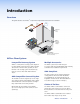
Introduction Overview This guide describes the AVTrac® components and provides instructions for installation.
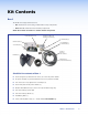
Kit Contents Box 1 The AVTrac Kit is shipped in three boxes. • Box 1 contains the connectivity, conduit and accessory components. • Boxes 2 and 3 contain the track and ramp components. Check the contents of each box to ensure all items are present.
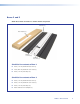
Boxes 2 and 3 Check the contents of each box to ensure all items are present. Side Ramp (2) Plastic Template (1) Aluminum Cover Track (1) Aluminum Base Track (1) Checklist for contents of box 2 4 feet (1.22 m) aluminum base track (1) 3 feet (0.91 m) aluminum cover track (1) 4 feet (1.22 m) side ramps (2) Checklist for contents of box 3 4 feet (1.22 m) aluminum base track (1) 4 feet (1.22 m) aluminum cover track (1) 4 feet (1.
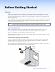
Before Getting Started Planning AVTrac can be installed before new carpeting is fitted or retrofitted under preexisting carpet. It can also be installed in new construction before the drywall and carpeting is in place. Retrofitting the track in a space with existing carpeting and furniture requires some extra preparation to remove the carpet and prepare the floor for laying the track.
Room Considerations Determine the A/V requirements for the room. Extron provides a complete range of AAPs that can be purchased separately to provide fully customizable central connectivity. Select the best configuration for existing furniture, equipment, cables and the AVTrac. It may help to mark the position of the track using a marker pen or tape. The connectivity box must be positioned under a podium or table to avoid creating a tripping hazard. AVTrac can be cut to meet the needs of the room.
Tools and Equipment Required Before Installation Almost everything you need to install your AVTrac system has been included. You will need some basic tools and materials depending on the facility and requirements. Visit www.extron.com for a full range of cables and components for populating the connectivity box. NOTE: All structural steps and electrical installation should be performed by qualified personnel in accordance with local and national building codes and local and national electrical codes.
Installation Step 1: Track By this point you must have decided exactly where the AVTrac will be installed, checked the contents of the kit, and gathered the tools that you will need. Extron recommends consulting a carpeting expert before removing the carpet. 1. Determine whether the installation will be in new construction, under preexisting carpet tiles or under preexisting carpet rolls, and follow the appropriate instructions.
Prelaid Carpet Rolls — Cut Carpet When the positioning of preinstalled furniture makes it impossible to remove existing carpet, the carpet must be cut (see the figure at right). Side Ramps Carpet a. Use tape to mark where the track and ramps will be positioned and make one straight cut (a) in the middle of where the base track will run (see the figure to the right). This cut must be the same length as the base track. b.
3. Using a drill and box cutters or a saw, cut a hole at the base of the wall 4 inches wide by 1½ inches high (10.1 cm x 3.8 cm). 4" (1 0.2 c 1½" (3.8 cm) If there is a metal base stud, use a hand saw or tin snips to cut it at both edges of the hole and bend it back into the hole so that the stud lies flat on the floor. Use a file to remove any jagged edges that might damage cables. m) The hole will eventually be covered by the baseboard, so it does not have to be perfect. 4.
5. Drill mounting holes in the shallow grooves of the base track and side ramps using a 1/4 inch bit for drilling metal (not supplied). NOTE: Mounting holes must be a maximum of 3 feet (91 cm) apart and one must be within 6 inches (15.2 cm) of each end of the track.
7. Lay the base track on the floor in the prepared location. Mate the tabs in the side ramps with the grooves in the base track, and place the end ramps in position at the end of the track furthest from the wall. 8. Using the provided masonry bit, drill 5/32 inch diameter by 1 1/2 inch deep pilot holes into the concrete through the predrilled mounting holes in the track and ramps. Tab on side ramp mates with groove in base track. Side Ramp Base Track Drill a 5/32” x 1 1/2” deep hole into concrete.
Step 2: Connectivity Box By this point, the base track, side ramps and end ramps must be securely fastened to the floor. To attach the connectivity box to the base track, follow these instructions: 1. Reposition the base of the connectivity box, in the correct orientation, over the predrilled holes in the base track (see sub‑step 6 in “Step 1: Track”). Mounting Holes (3 at the end closest to the wall) Masonry Screws The end of the connectivity box that has three mounting holes faces back towards the wall.
Step 3: AC Power Module By this point, the base of the connectivity box must be securely fastened to the floor. If your AVTrac system does not include the AC power module, ignore this section. To attach the AC power module, follow these instructions: 1. The AC power module must be positioned under the triple AAP socket that is closest to the track. a. Slide the power module side tabs into the slots on the side of the connectivity box. 6/32" Nut AC Power Module Tabs b.
Step 4: Architectural Adapter Plates (AAPs) At this point, the track, ramps and connectivitly box must all be securely in place. If an AC power module is required, it must be attached to the connectivity box and connected to an AC junction box. Do not turn on the power at this time. To attach the Architectural Adapter Plates (AAPs), follow these instructions: AAP R T H S IF H C T U T P C IN LE E S P M O U T E R IO D U A G B 5 8 0 x i S I A A P 1.
Step 5: Completing the Installation At this point, the track and connectivity box must be secured to the floor, the electrical power must be connected, and the AAP sockets must be populated. To complete the installation of the AVTrac, follow these instructions: 1. Lay the cables and power cords flat against the base track. If necessary, feed excess cable back into the wall. 2. Snap the cover track onto the base track. 3. Before cutting and gluing carpet, remove all dust and debris with a vacuum cleaner.
4. Glue or tape the carpet to the floor and side ramps. NOTE: Do not use the supplied tape to attach the carpet to the ramp. The tape is intended only for attaching the rubber inlay strip to the cover track. 5. Using the provided template, trim the wall baseboard to fit snugly around the track. 6. Attach the baseboard to the wall. 7. For model part number 42-156-24A, attach the provided rubber strip to the cover track raceway using double-sided adhesive tape (provided).
The figure below shows a completed AVTrac installation, which safely and discretely runs power, data, and A/V cables from a wall to a table, podium, or other furniture.
Specifications General Power �������������������������������������������� 125 VAC, 50-60 Hz, 20 A (max.
Connectivity box ���������������������� 3.55" H x 4.27" W x 12.0" L (9.0 cm H x 10.8 cm W x 30.
Reference Information Optional Accessories AVTrac Accessories Accessory Part Number AVTrac 4 feet Track Extension Kit 70-645-04 Connectivity Box (AAP Enclosure) 70-801-02 AC Power Modules (US) Prewired Conduit 70-799-08 AC Power Modules (Four US Outlets) Prewired Conduit 70-799-09 AC Power Modules (Central Europe) Isolated Cable 70-799-03 AC Power Modules (France) Isolated Cable 70-799-04 AC Power Modules (Australia) Conduit only 70-799-05 AC Power Modules (Universal Outlet) Isolated Cable
Extron® Warranty Extron Electronics warrants this product against defects in materials and workmanship for a period of three years from the date of purchase.
Installation Checklist Installation of the AVTrac can be divided into six main sections: Before Getting Started Open the three boxes containing the AVTrac kit and identify all the items provided (pages 2 and 3). Decide where the Track will be placed (pages 4 and 5) and, if necessary, prepare the site. Gather any additional tools needed for the installation (page 6). Step 1 — Install Track Remove the existing carpeting (pages 7 and 8). Cut a hole for cables in the drywall (page 9).