User Guide Architectural Connectivity AVTrac® Extension Kit Floor Mount Raceway System 68-1492-01 Rev.
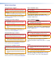
Safety Instructions Safety Instructions • English WARNING: This symbol, D, when used on the product, is intended to alert the user of the presence of uninsulated dangerous voltage within the product’s enclosure that may present a risk of electric shock. ATTENTION: This symbol, I, when used on the product, is intended to alert the user of important operating and maintenance (servicing) instructions in the literature provided with the equipment.
FCC Class A Notice This equipment has been tested and found to comply with the limits for a Class A digital device, pursuant to part 15 of the FCC Rules. Operation is subject to the following two conditions: 1. This device may not cause harmful interference. 2. This device must accept any interference received, including interference that may cause undesired operation.
Conventions Used in this Guide In this user guide, the following are used: WARNING: A warning warns of things or actions that might cause injury, death, or other severe consequences. ATTENTION: NOTE: Attention indicates a potential hazard to equipment or data. A note draws attention to important information. TIP: A tip provides a suggestion to make working with the application easier.
Contents Specifications Availability............................. iii Kit Contents.................................................... 1 Contents checklist........................................... 1 Before Getting Started................................... 2 Tools and Equipment Required for Installation................................................. 2 Tools............................................................. 2 Other Equipment.......................................... 2 Installation...........
vi AVTrac Extensions • Contents
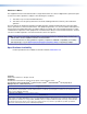
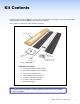
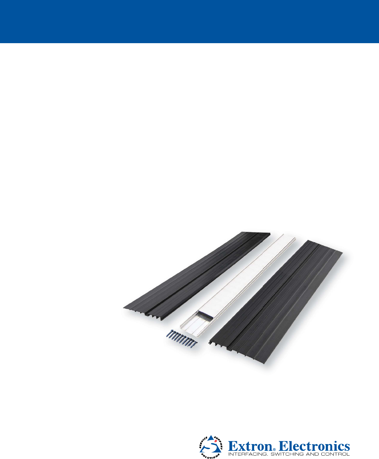
Kit Contents The AVTrac Extension kit is available as a 4 feet (1.22 meter) extension for the AVTrac system. An optional rubber strip inlay kit (part number 70-670-01) can be purchased separately. Check contents of each box to ensure all items are present. Side Ramp (2) Plastic Template (1) Installation Guide Aluminum Cover Track (1) Aluminum Base Track (1) 5/32" Masonry Bit (1) and 3/16" Masonry Screws Figure 1. Kit Contents Contents checklist 4 feet (1.
Before Getting Started Tools and Equipment Required for Installation Almost everything that you need to install your AVTrac kit has been included. You will need some basic tools and materials depending on the facility and requirements. NOTE: All structural steps and electrical installation should be performed by qualified personnel in accordance with local and national building codes and electrical codes.
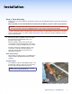
Installation Step 1: Track Mounting At this point you must already have checked the contents of the kit and gathered the tools that you will need for installation. Before installation, ensure that the Extension Kit matches the AVTrac product to make a proper junction. WARNING: Existing AVTrac rubber inlay models may be mismatched with the cover track of the extension kit. This mismatch may present a tripping hazard. Consult an Extron representative for advice.
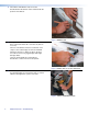
2. If the AVTrac will abut the wall, remove the baseboard from the bottom of the wall and mark the position of the AVTrac. Figure 3. Mark the wall. 3. Using a drill, box cutters, or a saw, cut a hole at the base of the wall 4 inches W x 1½ inches H (10.2 cm x 3.8 cm). If there is a metal base stud, use a hand saw or tin snips to cut it at both edges of the hole and bend it back into the hole so that it lies flat on the floor. Use a file to remove any jagged edges that might damage cables.
5. Pre-drill mounting holes in the shallow grooves of the base track and side ramps using a 1/4 inches bit for drilling metal (not supplied.) NOTE: Mounting holes must be a maximum of 3 feet (0.91 m) apart, and one must be within 6 inches (0.15 m) of each end of the track. Pre-drill holes in the shallow groove in the base track. Pre-drill holes in the shallow groove in the side ramp. Side Ramp Base Track Figure 6. Pre-drill the holes in the track and ramps. 6.
Step 2: Finishing Up At this point, the track must already have been secured to the floor. To complete the installation of the AVTrac, follow these instructions: 1. Lay the cables and power cords flat against the base track. If necessary, feed excess cable back into the wall. Snap the cover track onto the base track. Figure 10. Lay the cables flat and fit the cover track. 2. Before cutting and gluing the carpet, remove all dust and debris with a vacuum cleaner.
4. If the extension kit abuts the wall, use the provided template to trim the wall base board so that it fits snugly around the track. Figure 14. Use the template to cut the base board. 5. Attach the base board to the wall. Figure 15. Reattach the base board to the wall. 6. To insert a carpet inlay, cut a strip of the finished carpeting and glue or tape it to the cover track raceway. For an alternative rubber finish, use the optional rubber strip inlay kit (part number 70-670-01). Figure 16.
Reference Material Optional Accessories AVTrac Floor System To ensure a precise join when this kit is used with another AVTrac product, the two products must be compatible.
Extron Warranty Extron Electronics warrants this product against defects in materials and workmanship for a period of three years from the date of purchase; touchscreen display and overlay components are covered for 1 year.