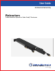
User Guide Architectural Connectivity Retractors Cable Retraction System for Cable Cubby® Enclosures 68-1784-01 Rev.
Safety Instructions Safety Instructions • English WARNING: This symbol, , when used on the product, is intended to alert the user of the presence of uninsulated dangerous voltage within the product’s enclosure that may present a risk of electric shock. ATTENTION: This symbol, , when used on the product, is intended to alert the user of important operating and maintenance (servicing) instructions in the literature provided with the equipment.
Copyright © 2013 Extron Electronics. All rights reserved. Trademarks All trademarks mentioned in this guide are the properties of their respective owners. The following registered trademarks(R), registered service marks(SM), and trademarks(TM) are the property of RGB Systems, Inc.
Conventions Used in this Guide Notifications The following notifications are used in this guide: DANGER: A danger indicates a situation that will result in death or severe injury. WARNING: A warning indicates a situation that has the potential to result in death or severe injury. CAUTION: A caution indicates a situation that may result in minor injury. ATTENTION: Attention indicates a situation that may damage or destroy the product or associated equipment.
Contents Introduction............................................................ 1 Operation............................................................... 21 About this User Guide......................................... 1 About the Cable Retraction System..................... 1 Features.............................................................. 1 Extend a Cable ................................................. 21 Retract a Cable.................................................
Cable Retraction System • Contents vi
Introduction • About this User Guide • About the Cable Retraction System • Features About this User Guide This guide contains information to install, adjust, and operate Extron Electronics Cable Retraction System for Cable Cubby® Enclosures, and the Extended Length Cable Retraction System for Cable Cubby® Enclosures.
•• Flexible installation alternatives — Retractor can be installed under a table or other work surface in either a vertical or horizontal position. •• DC Laptop Power — Refer to the retraction system DC power compatibility list on the website for laptop compatibility. Always use the power supply recommended by the laptop manufacturer. •• Filler Modules (optional) — For mounting fewer than three retractors on each side (fewer than two for the Cable Cubby 200).
Before Getting Started This section provides an overview of the retractor installation and suggestions for planning an installation. • Cable Retraction System Overview • Planning • Prepare the Cable Cubby Enclosure • Prepare the Retractors Cable Retraction System Overview Before beginning an installation, familiarize yourself with the system and the installation to determine if additional parts or accessories are required.
Planning The cable retraction system can be mounted horizontally or vertically depending upon under‑table clearance and accessibility. Horizontal mounting is recommended to provide maximum legroom and to protect the retractors against accidental damage. Vertical mounting is used where insufficient under-table space exists for horizontal mounting or where under‑table access is limited.
A Cable Cubby Series Installation Guide with details of the AAP bracket requirements, along with the horizontal mounting bracket, filler module, CC 200 mounting bracket kit, AAP brackets, and a laptop compatibility list are available at www.extron.com. CAUTION: • Do not operate a retractor until it is installed. • Keep hands away from moving parts.
For new Installations: Choose the optimal mounting location for the Cable Cubby enclosure. The final location may require some adjustment depending upon under-table clearances required for the retraction system. Once the location has been determined, follow the instructions provided with the enclosure for mounting and installing a power module and AAPs. For retrofit installations: For most retrofit installations, the Cable Cubby enclosure does not require removal.
TLP 350CV, TLP 710CV, TLE 350, TLE 710 Enclosure Clearances The following diagrams show the clearance dimensions required for mounting a retractor system in a TouchLink (TLP 350CV and TLP 710CV only) or the TLE series enclosures. 1.9" (4.8 cm) 1.9" (4.8 cm) 15.7" (39.9 cm) See Table A See Table B 10.0" (25.4 cm) 3.0" (7.6 cm) 16.7" (42.5 cm) 24.3" (61.7 cm) 30.3" (77.0 cm) 21.7" (55.0 cm) 10.0" (25.4 cm) 3.0" (7.6 cm) 23.0" (58.
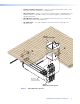
All Installations (Except Drop-in) Horizontal Mounting: Be certain the horizontal mounting bracket can be fastened under the table or on a table support without bending the pulley system or forcing it from perpendicular with the enclosure (see figure 7, “Top View”).
Prepare the Cable Cubby Enclosure DANGER: SEVERE ELECTRICAL SHOCK. Remove all power from the Cable Cubby enclosure before beginning a retraction system installation. All Installations By now you should be certain the retraction system has adequate under-table clearance for installation and that proper legroom will be provided to avoid accidental contact with the system.
Prepare the Retractors Each retractor is delivered ready to mount vertically. No further modifications are required. See CC 300, CC 600, CC 800, TLE, TLP Installation on page 14 for vertical installation details. Horizontal or Angular Mounting: To mount the retractors horizontally or at an angle, remove the two enclosure screws from the retractor (see figure 9). For horizontal mounting proceed to the “Installation” section beginning on page 11. For angular mounting, see below.
Installation This section provides details of the retractor system installation, cable connection, and verification of operation.
Cable Cubby 200 The CC 200 Mounting Bracket, part number 70-678-10, allows one or two retractors (standard or XL) to be installed in a Cable Cubby 200 enclosure. The bracket kit adapts an AAP opening for retraction system mounting similar to other Cable Cubby enclosures. Before installing the adapter, be certain there is adequate space under the table for the retraction system with the attached bracket.
CC 200 Bracket and Retractor Mounting 1. Using the supplied mounting bolt (1/4-20 x 3 inch), mount the CC 200 bracket to the retractor as shown. NOTE: If only one retractor is mounted, use a filler module (part number 70-678-08) in place of the second retractor. Once the retractor is mounted to the bracket, the assembly may be installed. 2. The cable stops and connectors may be too large to fit through the AAP opening at the same time as the retractor.
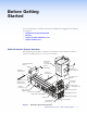
CC 300, CC 600, CC 800, TLE, TLP Installation The enclosure must be installed and properly configured before beginning the retraction system installation. 1. With the cable release buttons against the enclosure wall, install the retraction system by pushing the system up and into the enclosure (see figure 13). 2.
Horizontal Bracket Mounting For horizontal mounting, the horizontal mounting bracket (part number 70-678-00) must be used. The slotted holes in the mounting bracket allow for tolerance in placing the bracket. To ensure accurate bracket location, follow these procedures: 1. Attach the horizontal mounting bracket to the retractor end caps using the provided bolt and nut. TIP: Hand tighten the nut only enough to keep the bracket from easily moving. The bolt and nut will be removed later.
3. Ensure the bracket is flush with the surface and trace a line around the bracket perimeter. Trace Around Bracket Perimeter Figure 16. Mark Bracket Location 4. Lower the assembly and remove the horizontal bracket from the retractors. 5. Position the bracket inside the lines drawn in step 3 and fasten with the supplied screws. ATTENTION: Ensure the supplied screws do not pierce through the top of the table. If necessary, use appropriate screws based on the table material and thickness.
Locking Screw (Optional) If the retraction system is mounted next to an unused location in the Cable Cubby enclosure, a locking screw is provided to prevent the retractors from rotating on their mounting bolt during operation. If needed, tighten the locking screws to prevent movement of the retractor. There is one locking screw for each retractor. NOTE: Do not overtighten. The locking screw only needs to be snug. Tighten locking screw (1 each). Locking Screw Figure 18.
Alternative Solutions Drop-in Installations For installations with limited under-table access, the retractors must be installed before dropping the enclosure into the table. All drop-in installations must be mounted vertically or using angular mounting. 1. For retrofit installations, remove the Cable Cubby enclosure from the furniture. For new installations follow the Cable Cubby enclosure preparation instructions but do not mount the enclosure. 2.
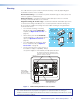
Laptop Power The DC power retractor provides a connection for a laptop on the tabletop to a compatible laptop power supply (not supplied) under the furniture. Installation of the retractor is identical to other retractors. The cable has a female connector under the furniture (b) for connection to a laptop power supply (a), and male connector on the topside (c) of the table for connection to a compatible laptop. ATTENTION: • Use only the power supply recommended by the manufacturer of the laptop.
Connect the Cables Connect the under-enclosure cables to the proper device. If additional cable length is needed use Extron cable as required. Excess cabling may cause clearance issues. Use wire ties to secure under-table cabling to prevent accidental contact or entanglement with users. Verify Cable Release Operation After installation, check the operation of the cable release assembly. Pull a length of cable from the system.
Operation This section provides details of the retractor system operation. • Extend a Cable • Retract a Cable Once installed, the retractors are ready for operation. CAUTION: • Do not operate a retractor until it is installed. • When retracting, hold the cable with one hand and press the release button with the other. • Retraction should be a slow, controlled motion. • Keep hands away from moving parts.
Retract a Cable 1. Disconnect the cable from the device and with one hand hold it firmly by the connector to keep the cable taught. 2. With your other hand, press and hold the cable release button. CAUTION: Use one hand to control the cable as it retracts. A cable allowed to retract too quickly and without control can cause possible injury to the user or damage the furniture surface, Cable Cubby, and nearby items. 3.
Maintenance and Adjustments • Pulley System Adjustment • Removing and Replacing the System • Expand the Cable Retraction System • Add a Cable Retraction System ATTENTION: • Each Extron retractor model is designed with custom-made cable and a unique matching spring that work together to maintain cable signal integrity and preserve consistent cable retraction pull force over the life of the product. Alterations to the retractor will cause premature failure of the retractor system and cables.
2. Hold the cable to prevent movement. 4 Adjust. Retainer Clip 3 Loosen thumbwheel 2 Hold cable. nut. Align pulley screw. 1 Cable stop collar (or connector on some models) must be seated. Figure 23. Pulley System Adjustment 3. Loosen the thumbwheel nut on the retainer clip until the cable can be moved. Do not allow it complete freedom of movement. 4. Adjust the cable to align the bottom pulley screw with the alignment hole on the enclosure (designated c on the product label in figure 24).
Removing and Replacing the System To Remove the System: DANGER: Ensure that AC power is disconnected before servicing the system. 1. Remove both ends of all retractor cables from connected devices. NOTE: Drop-in installations require removal of the enclosure and retraction system at the same time. 2. If necessary, loosen the locking screw on all retractors. If the system is mounted vertically, proceed to step 6. Loosen locking screw (1 ea). Figure 25. Loosen Locking Screws 3.
5. Slowly lower the system and allow it to hang vertically. If the system was mounted vertically, it is already in this position. 6. Make certain the retractors are supported so they will not drop unexpectedly. CAUTION: All retractors attached to the enclosure mounting bolt will drop when the enclosure mounting bolt is removed. 7. Remove the enclosure mounting bolt. The retraction system is now detached from the Cable Cubby. 7 Remove enclosure mounting bolt. 8 Slide system down and out.
Expand the Cable Retraction System Up to three retractors on each side, six total, (two total for the Cable Cubby 200), can be mounted in a retraction system installation. If fewer than the maximum are installed and additional retractors are desired, remove the filler module and replace it with the new retractor (see Removing and Replacing the System on page 25). Filler Module Figure 28.
Add a Cable Retraction System Depending upon the Cable Cubby enclosure, an additional retraction system with up to three more retractors may be installed. As in the initial retraction system installation, existing AAPs and their brackets may need to be relocated, removed, or replaced to allow room for the additional system. The additional system does not have to mount the same as the first, but proper under-table clearance for both systems, as well as clearances from each other must be considered.
Reference Information • Cable Retraction System Part Numbers • Optional Accessories Cable Retraction System Part Numbers Retractors are available in versions to support most AV and data signal types including VGA, Network, PC Audio, USB, DisplayPort, HDMI, and others. Each standard retractor provides cable that extends up to 3 feet (90 cm) from the enclosure. A 6 foot (1.
Extron Warranty Extron Electronics warrants this product against defects in materials and workmanship for a period of three years from the date of purchase.