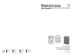
User’s Manual CTL208CM www.extron.com Extron Electronics, USA Extron Electronics, Europe Extron Electronics, Asia Extron Electronics, Japan 1230 South Lewis Street Anaheim, CA 92805 USA 714.491.1500 Fax 714.491.1517 Beeldschermweg 6C 3821 AH Amersfoort The Netherlands +31.33.453.4040 Fax +31.33.453.4050 135 Joo Seng Road, #04-01 PM Industrial Building Singapore 368363 +65.6383.4400 Fax +65.6383.4664 Daisan DMJ Building 6F 3-9-1 Kudan Minami Chiyoda-ku, Tokyo 102-0074 Japan +81.3.3511.7655 Fax +81.
Precautions Safety Instructions • English This symbol is intended to alert the user of important operating and maintenance (servicing) instructions in the literature provided with the equipment. This symbol is intended to alert the user of the presence of uninsulated dangerous voltage within the product's enclosure that may present a risk of electric shock. Caution Read Instructions • Read and understand all safety and operating instructions before using the equipment.
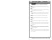
Quick Start Guide — CTL208CM CAUTION Installation and service must be performed by authorized personnel only. These units must be installed in accordance with national and local electrical codes. Step 1 Power off all devices and disconnect them from the power source, if necessary. Step 2 Run the serial cable between the control panel module’s installation location and the device to be controlled.
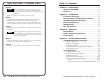
Quick Start Guide — CTL208CM, cont’d Table of Contents Chapter 1 • Introduction .......................................................... 1-1 Step 10 If the rear of the control panel module will be inaccessible when the installation is complete, the module should be powered up and its operation should be tested before the final installation. Apply or connect power to all devices in the system.
Table of Contents, cont’d Appendix • Reference Information .................................. A-1 Specifications ......................................................................... A-2 Parts List .................................................................................... A-3 Included parts ........................................................................ A-3 Mini-AAP mounting options ................................................. A-3 Wall mounting solutions .........................
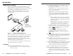
Introduction, cont’d Introduction About the CTL208CM The Extron CTL208CM is a programmable 8-button control panel module that can be connected to any serial-controlled device (figure 1-1). Each button can store one or two command strings that are programmed with either ASCII or hex characters. When you push the button, the control panel module issues the programmed ASCII or hex string to the connected device.
Introduction, cont’d CTL208CM Control Panel Module 2 Chapter Two Installation Installation Overview UL Requirements for Wall Box Installation Wall Mounting Site Preparation Device Configuration Wall Mounting Rear Panel Setup 1-4 CTL208CM Control Panel Module • Introduction
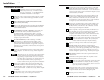
Installation, cont’d Installation Installation Overview CAUTION If desired, order a custom engraved front panel. Contact the Extron S3 Sales & Technical Support Hotline to order the panel. 2 Power off all devices and disconnect them from the power source, if necessary. 3 Run a serial cable between the site where the CTL208CM control panel module will be installed and the site of the serial-controlled device.
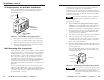
Installation, cont’d UL Requirements for Wall Box Installation The following Underwriters Laboratories (UL) requirements pertain to the installation of the CTL208CM into a wall or furniture (figure 2-1). Installation Cable The installation must conform to national and local electrical codes and to the equipment’s size requirements. Installation using a UL listed wall box (available from Extron) is recommended for most mounting options, but the optional wall mounting bracket can be used instead.
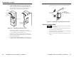
Installation, cont’d 5b. If you are using a wall box, insert the wall box into the opening, and attach it to the wall stud or furniture with nails or screws, leaving the front edge flush with the outer wall or furniture surface (figure 2-3). The illustration applies to both two-gang and four-gang wall boxes. clips that fasten the ring to the wall or furniture (figure 24).
Installation, cont’d Wall Mounting The physical orientation of the control panel module is important when you are programming and operating the buttons. Buttons 1 and 5 (figure 2-5) are on top when the CTL208 is right-side up. Orient the CTL208 so that the text on the rear of the unit is right-side up to determine the top of the module. Button number Button number 1 5 2 6 3 7 4 8 2. If not already accomplished, attach the power and serial cables to the rear of the control panel module.
Installation, cont’d Serial port connector — This port is a 3.5 mm, 5-pole captive screw connector for serial RS-232, RS-422, or RS-485 communications. Connect to the port as shown in figure 2-7. 1 The default settings for all switches for an RS-232 connection is off (0). DIP switch 3 should be turned on for an RS-485 full duplex connection only, and only if the CTL is the first or last unit in a daisy chain.
Installation, cont’d CTL208CM Control Panel Module 3 Chapter Three Operation Button Modes Send Programmed Commands Factory Reset 2-12 CTL208CM Control Panel Module • Installation
Operation, cont’d Operation Button Modes Send Programmed Commands Before a control panel module button is programmed, it has no function. See chapter 4, Serial Communications, to program the buttons. Programming includes: • Assigning the program string(s) to the button. One or two strings (primary and secondary) can be assigned to each button. • Setting each program string to be either ASCII or hexadecimal. • Setting the mode for each button.
Operation, cont’d • Toggle mode and a timeout set — Push a button to send the primary program string. The button’s LED lights. When you push the button a second time or when the timeout expires, the control panel module sends the secondary program string. The button’s LED goes out If you push the button a third time, the timeout interval starts over; that is, if the timeout is set to 30 minutes, the control panel module will send the secondary string 30 minutes later.
Serial Communications, cont’d Serial Communications The control panel module must be programmed before it can be operated. Programming can include setting several serial port variables to match the device to be controlled and includes entering the primary and secondary (if applicable) code for each button. You can program the control panel module either by using the ICS100 windows control program or by sending individual ASCII commands.
Serial Communications, cont’d a. Click in the appropriate radio buttons to select the desired settings. b. Click Ok. If you change the serial protocols, communications between the computer and the control panel module are lost until the computer is updated to match the new control panel module settings). 4. Using the software to program the CTL208CM Use the control program to program the CTL208 buttons as follows: 1. Click Inline Model > Select Address. The Addresses window (figure 4-3) appears.
Serial Communications, cont’d 3. 4. For each button to be programmed, click the pull down menu above the numbered panel button and select a mode: 0 Single, 1 Toggle, 2 Press/Release, or 3 Continuous. See Button Modes in chapter 3, Operation, for definitions of the various button modes. For each button to be programmed, click the numbered panel button. a. 5. Selecting the Hex radio button causes the CTL to convert the primary code that you will enter in step 6 to a hex value before saving it.
Serial Communications, cont’d Buttons must be set to operate in toggle mode to assign groups. Groups cannot be assigned to buttons that are set to operate in toggle mode and are assigned a timeout value. 11. When all of the desired programming changes are made, click the Program button at the bottom of the window to send all of the programming entries to the control panel module. End the session by selecting a different address than the one assigned to the CTL208.
Serial Communications, cont’d Symbols Control panel module responses When a command is valid, the module performs the command and sends the following response: X1 = Line feed = Address number [R0 {address} {echo of the command sent}] The very first command that you send to the control panel module must be the connect, [CC X1 ], command, where X1 is the module’s address. The control panel module will not accept other commands or respond until it has been addressed.
= Duplex mode: 0 = full duplex, 1 = half duplex (default) X15 = Front panel and responses: 0 = disable, 1 = enable (default) X16 = Reset level: 0 = reset the serial port to 9600 baud, no parity, Xoff, and half duplex mode; reset the address to 97; and enable the front panel. 1 = perform all of the same resets AND erase all button codes, reset all buttons to single mode, and reset all button groups and timeouts to 0.
4-14 (host to CTL208) (CTL208 to host) ASCII Command Response [SWM X2 [SWM?] CTL208CM Control Panel Module • Serial Communications Assign button groups •] Sets the button’s operating mode. See Button Modes in chapter 3, Operation for definitions of the button modes. X2 is valid between 01 through 08 and 11 through 18. Set button 1 to toggle mode. X9 8 indicates button 1’s group, indicates button 8’s group. Assign buttons 1, 2, 3, and 5 to group 1.
4-16 [FP1] [FP] [FP?] Enable front panel (default) Toggle front panel lockout View front panel lockout X1 •FP0•] [DFLT X16 ] View architectural information [ARC] Architectural information Reset control panel module [R0• X1 •ARC• X17 {none} [RES0] Disable serial responses Control panel module reset {none} [RES1] [R0• X1 •RES1•] [R0• X1 •FP?• X15 ] [R0• X1 •FP1•] [R0• X1 •FP•] [R0• (CTL208 to host) Enable serial responses Enable/disable responses [FP0] (host to CTL208) ASCII Command Re
Reference Information, cont’d Reference Information Specifications Control/remote Serial control port ........................ 1 RS-232, RS-422, or RS-485, 5-pole captive screw connector Baud rate and protocol ............... 1200, 2400, 4800, 9600 (default), 19200, or 38400 baud; 8-bit; 1 stop bit; no parity (default), even parity, or odd parity; half (default)/full duplex Pin configurations RS-232 ................................ 3 = TX, 5 = RX, 1= Gnd RS-422/RS-485 ..................
Reference Information, cont’d Architectural solutions Description Part number RGB 468 Mxi (black) 60-591-02 RGB 468 Mxi (white) 60-591-03 CIA111 (black, with cable guards) CIA111-1 CIA111 (white, with cable guards) CIA111-2 CIA111 (black, without cable guards) CIA111-3 CIA111 (white, without cable guards) CIA111-4 CIA112 (black, with cable guards) CIA112-1 CIA112 (Inline white, with cable guards) CIA112-2 CIA112 (black, without cable guards) CIA112-3 CIA112 (Inline white, without cable