
User`s manual


HDMI 201 Tx/Rx • Installation and Operation
Installation and Operation, cont’d
2-30
HDMI 201 Tx/Rx • Installation and Operation
2-31
Troubleshooting
HDMI signals run at a very high frequency and are especially
susceptible to bad video connections, too many adapters,
or cables that are too long. To avoid the loss of an image or
introduction of image jitter, follow these guidelines:
• The HDMI cable on the input to the transmitter or
the output of the receiver should not exceed 10' (3 m).
• Use only cable designed for HDMI signals.
• Limit or avoid the use of adapters.
• If the display exhibits a ashing black or blue screen,
snow, or other distortion, a non-HDCP compliant display
may be receiving an HDCP-encrypted signal.
Check for an HDCP problem by ejecting the DVD from
the player. If the display distortion stops and the DVD
menu or screen saver image is clear, the problem is
HDCP-related.
• The HDMI 201 works as described in point-to-point
applications. Do not use any additional adapters, patch
panels, or couplers with the input HDMI cables, output
HDMI cables, and/or twisted pair cables. Additional
links in the signal chain can result in the reduction of
signal integrity and overall cable length performance.
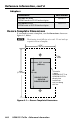
Application Examples
Audio conversion
Figure 2-27 shows a standard installation with HDMI video and
an audio input. The HDMI 201 A D Tx converts the video input
into two proprietary TP outputs. The Tx outputs the audio
directly on a captive screw connector.
POWER
12V
0.4A MAX
12
HDMI OUTPUT
RS-232
PASS THRU
Tx Rx
HDMI 201 Rx
INPUT
RS-232
PA SS THRU
AUDIO-R
HDMI
AUDIO-L
POWER
12V
0.4A MAX
DO NOT
CONNECT
TO LAN
1
2
O
U
T
P
U
T
S
HDMI 201 A D Tx
L
AUDIO
OUTPUT
R
Rx
Tx
HDMI In
Source
Audio
TP1
TP2
Balanced Audio Out
Balanced Audio
Wiring
Audio System
HDMI 201 A D Tx Front
HDMI 201 A D Tx Rear
HDMI 201 Rx
Projector
R+
R-
L+
L-
Figure 2-27 — Typical installation