User Guide Audio Products Mixers and Processors DMP 64 Digital Matrix Processor 68-1790-01 Rev.
Safety Instructions Safety Instructions • English WARNING: This symbol, , when used on the product, is intended to alert the user of the presence of uninsulated dangerous voltage within the product’s enclosure that may present a risk of electric shock.
FCC Class A Notice This equipment has been tested and found to comply with the limits for a Class A digital device, pursuant to part 15 of the FCC rules. The Class A limits provide reasonable protection against harmful interference when the equipment is operated in a commercial environment. This equipment generates, uses, and can radiate radio frequency energy and, if not installed and used in accordance with the instruction manual, may cause harmful interference to radio communications.
Conventions Used in this Guide Notifications The following notifications are used in this guide: DANGER: A danger indicates a situation that will result in death or severe injury. WARNING: A warning indicates a situation that has the potential to result in death or severe injury. CAUTION: A caution indicates a situation that may result in minor injury. ATTENTION: Attention indicates a situation that may damage or destroy the product or associated equipment.
Contents Introduction .................................................... 1 About This Guide.............................................. 1 About the DMP 64 Digital Matrix Processor...... 1 Features........................................................... 2 DMP 64 Application Diagram............................ 4 Installation ...................................................... 5 Mounting the DMP 64...................................... 5 Rear Panel Features and Cabling......................
Presets........................................................... 81 Previewing and Recalling a Preset.............. 81 Building a Preset......................................... 82 Protected Configuration.................................. 84 Save Protected Configuration..................... 84 Recall Protected Configuration................... 84 Change PIN................................................ 84 DSP Configurator Windows Menus................ 85 Keyboard Navigation...............................
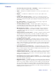
Introduction This section describes this manual and the DMP 64, including: • About This Guide • About the DMP 64 Digital Matrix Processor • Features • DMP 64 Application Diagram About This Guide This guide contains installation, configuration, and operating information for the Extron Electronics DMP 64 ProDSP™ Digital Matrix Processor, software-controlled digital audio processor. In this guide, the DMP 64 can also be referred to as “the mixer” or “device.
Features • Consumer and professional audio compatibility — Input and output line level can be set to consumer (–10 dBV) or professional (+4 dBu). • Inputs — Six balanced or unbalanced mic/line on 3.5 mm, 3-pole captive screw connectors. • Outputs — Four balanced or unbalanced on 3.5 mm, 3-pole captive screw connectors.
• Group masters — The DMP 64 provides the capability to consolidate gain or mute control throughout the system. Any gain or mute block within the Graphical User Environment can be selected and added to a group master, which can then be controlled by a single master fader and mute control. Each group master can have up to 16 blocks, and up to 32 group masters can be created. • Soft limits — Soft limits can be applied to group master faders.
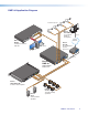
DMP 64 Application Diagram Desk Microphones R VC D DV C DO M CA P TO LAP PC ON F OF Y PLA DIS TE MU EN RE SC UP UT Extron TLP 700TV 7" TouchLink™ Tabletop Touchpanel -232 TP OU RS A B L R L 6 IO UD 3 5 T PU 4 8 IN R 7 A 2 1 UT TP OU B RG RY, B- Y TED LIS 3 1T2 . U S I.T.
Installation This section describes the installation of the DMP 64, including: • Mounting the DMP 64 • Rear Panel Features and Cabling Mounting the DMP 64 The 1U high, half rack width, 9.5 inch deep DMP 64 Digital Matrix Processor can be: • Set on a table, • Mounted on a rack shelf, • Mounted under a desk or tabletop, or • Mounted on a projector bracket. For detailed mounting options and UL rack mounting guidelines (see Mounting the DMP 64 on page 139).
Power connector — Connect the included 12 VDC external power supply into the 2-pole 3.5 mm captive screw connector. Be careful to observe the correct polarity. Smooth Ridges A A 2-Pole Orange Captive Screw Connector (12V) SECTION A–A Power Supply Output Cord Tie Wrap a 3/16” (5 mm) Max. Smooth Ridges Figure 2. Power Supply Wiring Use the supplied tie-wrap to strap the power cord to the extended tail of the connector.
b Mic/Line 1-6 input connectors — 3-pole 3.5 mm double-stacked captive screw connectors accept balanced or unbalanced mono mic or line level signals. Mic/line inputs provide gain settings to accommodate consumer (–10 dBV) and professional (+4 dBu) operating line level sources, plus microphone level sources. Up to six mono microphones or line inputs, balanced and unbalanced in any combination can be connected to these inputs. See the following diagram for wiring instructions. 3" 16 (5 mm) MAX.
e Digital I/O output connectors — A double-stacked 4-pole 3.5 mm captive screw connector provides six configurable digital input or output ports allowing connection to various devices such as motion detectors, alarms, lights, LEDs, buttons, photo (light) sensors, or temperature sensors. Digital I/O ports are used to monitor or drive TTL level digital signals. The inputs can be configured to operate in one of two modes: digital input or digital output.
Hardware Operation This section describes the the operation of the DMP 64, including: • DMP 64 Operation • Front Panel Operation • Rear Panel Operation DMP 64 Operation The DMP 64 does not have physical controls. Configuration and operation are accomplished using a PC running Windows XP or newer and the DSP Configurator software (available on the included disc or at www.extron.
Front Panel Operation a b c d INPUTS OUTPUTS CLIP CLIP SIGNAL CONFIG 1 2 3 4 5 6 SIGNAL 1 2 3 4 DMP 64 DIGITAL MATRIX PROCESSOR Figure 7. DMP 64 Front Panel a Power LED — The power indicator lights when the DMP 64 is operational. b Configuration connector — The USB 2.0 port uses a mini type-B connector to connect to a host computer for control. The DMP 64 USB driver must be installed prior to using the port (see Install the USB Driver on page 17).
Rear Panel Operation a 5 b Figure 8. 6 1 MIC +48V 2 3 4 5 6 c 2 RS-232 (1) 1 2 3 G 4 3 4 5 6 G d REMOTE 4 1 3 I/O 12V 1.0A MAX MIC/LINE INPUTS POWER 2 OUTPUTS 1 DMP 64 Tx Rx G RS-232 (2) LAN RESET Tx Rx G e f g hi DMP 64 Rear Panel a b d e f See Rear Panel Features and Cabling on page 5 for details. c Phantom Power indicators (MIC +48V) — These green LED indicators light solid when +48 V phantom power is placed on the corresponding mic/line input.
Reset Actuator and LED Indicator A recessed button (h) on the rear panel initiates several reset modes. The rear panel LED (i) blinks to indicate the reset mode. 3 4 5 6 1 MIC +48 V 2 3 4 5 6 1 2 3 4 RS-232 (1) 1 2 3 G 4 5 6 G REMOTE 2 I/O 12V 1.0A MAX MIC/LINE INPUTS POWER 1 OUTPUTS Rear Panel DMP 64 Tx Rx G LAN RESET RS-232 (2) Tx Rx G h Figure 9.
MODE 4 — IP Address reset: 1. Apply power to the DMP 64. 2. Press and hold the reset button about 6 seconds until the reset LED blinks twice. Release the reset button. 3. Within (1) second, press the reset button again to reset the IP settings. If a momentary press does not occur within 1 second, the reset will be ignored. Mode 4 will: • Enable ARP program capability • Set the IP address back to factory default (192.168.254.254) • Set the Subnet back to factory default (255.255.0.
DMP Software This section describes the control software for the DMP 64, including: • Software Control • Embedded Web Pages • Windows-based Program Control • DSP Configurator Program Basics • Audio level, Mix-point, Processing Blocks, and Signal Chains • Mic/Line Input Signal Controls • Ducker Tutorials • Line Output Channels • Virtual Bus Returns • Primary Mix Matrix • Secondary Mix Matrix • Group Masters • Digital I/O Ports • Emulate Mode and Live Mode • Presets • Protected
Embedded Web Pages The embedded web pages, accessible by LAN using a web browser, include the following information, available in a tabbed interface. • System Status — The opening web page, displaying a report of system status parameters. • Configuration — This tab contains the following menu items. • System Settings. Contains IP address and date/time settings. • Passwords. Enter/re-enter admin and user password fields to set up password protected access. • Firmware Upgrades.
2. Click the Software tab or software icon. NOTE: If the DVD setup program does not start automatically, run Launch.exe from the DVD ROM directory using Windows “My Computer”. Figure 10. DVD Software Menu 3. Scroll to the DSP Configurator program and click the Install text to its right. Figure 11. DVD Control Software Menu 4. Follow the on-screen instructions. By default, the installation creates a C:\Program Files\Extron\DSP_Configurator folder for the DSP Configurator program. 5.
Install the USB Driver When the USB installer begins, follow these instructions. 1. When the driver installation window appears (see figure 12), click Next to proceed. Figure 12. USB Installer Splash Screen 2. The driver installer launches (see figure 13). Figure 13.
3. When the installer has completed the installation of the USB drivers, the following screen appears (see figure 14): Figure 14. Successful USB Driver Installation 4. Click Finish. USB driver installation is complete. DSP Configurator Program Basics Starting the Program NOTE: Extron recommends connection via the Ethernet LAN port for running the DSP Configurator program. To run the DSP Configurator Program, click Start > Programs > Extron Electronics > DSP Configurator > DSP Configurator.
a b c h d e f g i j Figure 15. DMP 64 Configurator Program The DSP Configurator program window consists of an input and virtual return signal processor chain, the main mixer, virtual send and receive (secondary) mixers, and an output signal processing chain.
Navigation There are two methods of navigation around the interface: • Keyboard • Mouse One element in the user interface always retains focus. When a new DSP Configurator file is opened, the upper left element (Input #1 Gain) is focused by default. Keyboard Navigation All user interface elements, including mix-points, have the ability to receive focus using the tab and arrow keys or using the arrow keys following a single left-click. For additional details (see Keyboard Navigation on page 85).
As shown below, the starting point for the paste, (the upper, leftmost element), must first be focused by left-clicking the mouse on it. Note the green focus outline that appears on the Mic #4 Gain block. The clipboard elements are pasted using the context menu Paste command, the Edit>Paste command, or . NOTE: A cut and copy of elements can be pasted to multiple locations. To copy the clipboard to an additional location, click on the leftmost block and paste again.
DSP Configurator Toolbar Menus The DSP Configurator contains the following structural menus, arranged horizontally below the title bar: File NOTE: New, Open, and Recent Files are unavailable in Live mode. • New — Discards the current DSP configuration (after prompting to save any changes) and opens a blank configuration file. • Open — Loads and activates a previously saved DSP configuration file. • Save — Saves all changes to the current DSP configuration file under the current file name.
View • Meter Bridge — Opens a Meters dialog box with real-time meters that monitor signal levels at each input and output. NOTE: Meter Bridge is available in Live mode only while connected using the LAN port. Figure 16. Meter Bridge • Re-enable all dialogs — Re-enables all dialog boxes, the pop-up windows that allow changes to block parameters. • Error log — Lists error messages as a troubleshooting tool. • Group Controls — Opens the Group Controls dialog box (see Group Masters on page 69).
• Configure Digital I/O Ports — Live mode only. Opens a utility to configure digital I/O ports. The DMP 64 provides six digital I/O ports that can be used to trigger external events from DMP 64 actions, or for external events to trigger DMP actions (see Digital I/O Ports on page 75). • Connect to/Disconnect from Device (depending on Emulate or Live mode) — Performs the same functions as the Mode Emulate and Mode Live buttons.
• Processor Defaults, Reset All Defaults — Returns the DMP 64 processor and level control blocks to factory default settings. Each processor and gain/volume/trim block also has an individual default reset. • Processor Defaults, Defaults — Individually selects the default parameters for the various processor, trim, and gain blocks. Each row item contains default settings customized for the processor, filter, trim, or gain block it represents.
Presets Drop-down Displays a list of up to 32 presets. Select a preset from the list to display it in the window and either activate it (Recall), abort the selection without either recalling or deleting it (Cancel), or delete it (Delete). NOTE: An asterisk in the drop-down list indicates a partial preset exists only in the DMP 64 and has not been uploaded to the DSP Configurator. Mode Buttons Provides selection between Live mode and Emulate mode.
a b c h d e f g i j Figure 17. Control Blocks and Processor Chains Audio Level, Mix-point, Processing Blocks, and Signal Chains Outlined in red above (see figure 17), all control blocks on the main DSP user interface have one of three main functions in the overall signal chain: • Level control (gain, trim, and volume), • Mix-point (signal routing), or • Signal processing (filter, feedback, dynamics, delay, duck, and loudness).
Level Control Blocks To access a gain, trim or volume control to view a setting, make a change, or observe a live audio meter (input gain and output volume blocks only), double‑click the gain block icon (see figure 19). This action opens a dialog box that contains the fader for that control. Double-click a gain, trim, or volume control. A dialog box opens, containing the full fader control. NOTE: In Emulate mode (the startup mode), the meter is not operational. Figure 19.
Once a processor is inserted, to view associated parameters that define the selected processor (such as a frequency curve) or to remove the bypass, double‑click on the processor block. This action opens a new window with a dialog box that contains parameters for the processor (see figure 21). Figure 21. Sample Processor Dialog Box • The Set Defaults button discards all custom settings and reloads the default parameters.
Mic/Line Input Signal Controls The input signal processor chain allows adjustments to program or microphone audio material before input to the main mixer. Gain Control (GAIN) The gain control provides a single long-throw fader with a range of –18 dB to +80 dB, adjustable in 1 dB increments with the fader, or in 0.1 dB increments using direct entry in the input signal level readout below the fader.
Filter (FILT) Each filter block allows a total of five filters. The first filter is inserted from a processor list that appears when the block is double‑clicked or from a context window that shows a processor list when the block is right‑clicked. Figure 22. Insert Filter Menu Once inserted, double‑click the processor block to change parameters of the filter. After the first filter is inserted, up to four additional filters can be added to the filter block using the dialog box.
Figure 23. Filter Block Dialog Box Additional filters are inserted using the open filter block dialog box, and selecting a filter type from the drop-down filter selection list. All filter parameters are modified using the Filter block dialog box. Each filter is loaded with all applicable default parameters displayed to the right of each drop-down filter selection list.
Figure 24. Filter Dialog Box, Filters Added Within the dialog box, a filter is focused when a filter type is inserted, or is focused by clicking the filter number to the left of the filter selection drop-down list. Note how box 3 (see figure 24) is highlighted in yellow, indicating it is the filter in focus. When bypassed, the results of the filter in focus (independent of other filters) will show in the graph as a dotted line the same color as its filter row. When active (not bypassed), the line is solid.
Figure 25. Filter Dialog Box, Filter Not Bypassed Above the graph, each filter has a "handle" (circled in red above for the parametric EQ filter) placed directly above the cutoff or center frequency. The handle number corresponds to the filter number (also outlined in red). Clicking a handle or clicking the table row brings focus to that filter. the handle horizontally changes the cutoff or center frequency to a new position on the x axis.
High Pass The high pass filter allows frequencies below the specified frequency to pass unattenuated. All frequencies below the cutoff are attenuated. The default cutoff is 100 Hz. Figure 26. High Pass Filter Response Curve All frequencies lower than the specified frequency (in this example,100 Hz) are attenuated leaving the upper frequency response flat. Also note that at the specified frequency (100 Hz) the signal is 3 dB down, typical operation for high pass filters.
Low Pass The low pass filter is the opposite of the High Pass filter. All frequencies above the specified frequency are attenuated allowing lower frequencies to pass. Figure 27. Low Pass Filter Response Curve Here, the frequencies higher than the specified frequency, 10 kHz, are attenuated leaving the lower frequency response flat.
Bass and Treble Shelving Bass and treble shelving can be added to the filter. Also known as shelving or tone controls, the separate bass and treble filters provide the ability to cut or boost gain linearly above or below a selected frequency, with the end-band shape giving the visual appearance of a shelf. Adding the filter automatically inserts both a bass and a treble control row.
Parametric (Equalizer) The parametric filter is a frequency equalizer that offers control of all parameters, including amplitude (the amount of gain [boost], or gain reduction [cut] applied), center frequency (frequency), and range of affected frequencies (Q) around the center frequency. Up to five parametric filters can be placed in the filter box at one time. Each can be set to a different frequency creating a five band parametric equalizer. The control boosts or cuts the center frequency.
By increasing the Q to 10.000, the center frequency remains the same. The markers show the bandwidth of the filter narrowed to between 900 Hz and 1200 Hz, or about 300 Hz (see figure 30). Parametric filters can be used to notch out a very narrow, or very wide range of frequencies using the Q setting. Figure 30. Parametric Filter at 1000 Hz, Q: 10.000 The dialog window above shows the frequency curve for a single active filter.
The overall frequency response is now shown as a solid red line with the filter in focus (located in row 3 in figure 31) shown in the color of its table row. Figure 31. All Parametric Filters Active The parametric filter allows frequency selection accurate to 0.1 Hz and either 6 or 12 dB of slope. The 3 dB down point remains constant regardless of the slope setting. Only the steepness of the frequency attentuation curve changes.
Feedback Suppressor (FBS) The Feedback Suppressor is used in live situations when there is an indication of feedback during live operation. Dynamic filters automatically detect feedback on a live microphone channel, and engage a set of up to 5 fixed and 15 dynamic filters to counteract frequency peaks at the detected feedback frequency. Up to 15 separate filters can be employed at any time. The 15 filters act in a FIFO (first in, first out) rotation.
FBS Settings The Settings tab enables selection of the feedback suppressor parameters. • • For Composite View show: — The graph view is set by one of three buttons: • Only Dynamic FBS Filters • Only Fixed FBS Filters • Dynamic & Fixed FBS Filters (default) Mode: Q — Adjusts the notch filter Q used by dynamic filters. Similar to the parametric filter Q, it changes the bandwidth of the filter. The default setting can be modified in Tools>Options. The range is from 5 to 65.
FBS Dynamic Filters This tab contains the fifteen dynamic filters, with a scroll bar to display filters hidden due to dialog box size. Dynamic filters are notch filters that are cut only, providing attenuation up to 30 dB at the specified Q. The default Q is set in the Tools>Options menu, but can be changed on the settings tab prior to engaging the FBS dynamic filters. Changing the Q setting after dynamic filters have been generated clears all dynamic filters. Figure 34.
FBS Fixed Filters Fixed filters are notch filters with an adjustable center frequency and Q, and up to 30 dB of cut. The fixed filters are typically set by converting dynamic filters to fixed, however adjustments to filter parameters can be made manually from the Fixed Filters tab. Fixed Filters are inactive and the filter type is set to Unused by default. Figure 35. FBS Fixed Filters Tab No filter parameters are displayed when the filter type is set to Unused.
Dynamics (DYN) A dynamics processor alters the dynamic range, the difference between the loudest to the quietest portions, of an audio signal. Each input channel provides two dynamics processor blocks that, when inserted, provide one of four types; AGC, Compressor, Limiter, or a Noise Gate processor. To insert a processor into an empty block, select Insert from the processor menu.
Automatic Gain Control (AGC) AGC adjusts the gain level of a signal based upon the input strength to achieve a more consistent volume. Below the set threshold, the signal is not affected. Above the threshold, weaker signals are boosted up to the maximum gain setting to reach a user‑defined target level. As the signal approaches the target level it receives less gain or no gain at all. Once the signal reaches the target level all gain is removed. Click in each field to change the values.
Compressor The compressor regulates signal level by reducing (compressing) the dynamic range of the input signal above a specified threshold. The input level to output level ratio determines the reduction in the dynamic range beyond the threshold setting. For example, with a ratio setting of 2:1, for every 2 dB of input above the threshold, the compressor outputs 1 dB. Compression is commonly used to contain mic levels within an acceptable range for maximum vocal clarity.
Limiter The limiter restricts the input signal level by compressing its dynamic range above a specified threshold. The limiter is most commonly used to prevent clipping, protecting a system against component or speaker damage. While the limiter is closely related to the compressor, it applies a much higher compression ratio of ∞:1 above the threshold. The ratio is fixed and cannot be changed. Click in each field to change the value.
Noise Gate The noise gate allows an input signal to pass only when it exceeds a specified threshold level. Above the threshold level, the signal passes unprocessed. Below the threshold the signal is attenuated at the rate set by the ratio adjustment. The typical setting of the noise gate threshold is just above any noise level in the environment or source equipment. That allows signals that are above the noise to pass, and attenuates the noise when there is no signal, eliminating background noise.
Delay (DLY) The delay processor, when inserted, provides a means to delay the audio signal. Audio delay syncs audio to video or can time-align speakers placed at different distances from the listener. The DMP 64 can set delay by either of two criteria: time or distance (feet or meters). The default units setting is time with a range of 0.0 ms to 200.0 ms adjustable in 0.1 ms steps. Default is 100.0 ms. Settings are controlled with a vertical slider and indicated with a value readout field.
Ducking (DUCK) Ducking provideds a means to duck, or lower, the level of one or more input signals when a specified source must take precedence. The ducking processor block, when inserted, provides a means to duck one or more mics and program material (ducking targets) when the processor detects a signal from the ducking source.
Ducking Configuration Ducking is configured in a dialog box that opens when an active ducking processor block is double-clicked (see figure 37 on the previous page). a b Current source indicator Shows the input selected as the ducking source. Ducker settings affect the input channel shown here. When a ducker dialog is opened for a channel, the current source defaults to that channel. The current source can also be selected by the priority readout/source selector (see below).
e Priority f By (dB): (Target gain reduction amount) g Mix Status (for virtual returns): Displays the hierarchy of ducking source to duck targets (see Ducking Priority below). Priority levels are displayed in tree fashion. Click an input channel to select that channel as the current source. The current source indicator (a) reflects the selected input channel. Individual attenuation settings for each duck target in dB. If additional attenuation of a target is required, increase this value.
Ducker Tutorials The examples below are based on different input configurations. Insert a ducker from a ducker processor block using one of the following methods: Double-click the block, then click Ducker -or- Right-click the box to open context menu, then click Insert Ducker Once inserted, double-click on the ducker block to open the ducker configuration dialog box. The Enable Mic/Line Source box is checked. Ducking and Priority Ducking The first inserted channel ducks all selected targets.
Pre-mixer Gain (GAIN) The post-input processing gain control (also called the pre‑mixer gain) provides gain or attenuation post-processing gain block. It includes a mono long-throw fader with a – 100.0 to +12.0 dB gain range, and a current level setting readout below the fader. Fader adjustments are in 1 dB increments, while adjustments can be entered manually to 0.1 dB resolution. Default is unmuted at unity (0.0 dB) gain.
Line Output Channels There are four mono line output channels. Controls and processing blocks, identical for each output channel, are described in the following sections. Loudness (LOUD) The loudness processor, when inserted, applies a filter compensation curve to the signal in an inverse relationship to the output volume control setting. The higher the gain setting, the less loudness compensation is applied.
Calibrating Loudness The user can fine-tune the amount of loudness compensation using the compensation adjustment slider and adjusting "by ear," or by measuring SPL levels in a particular room, then using the slider to adjust the loudness filter relative to the SPL of the room and system gain structure. Before calibrating loudness, set up the system gain structure (see Optimizing Audio Levels on page 88).
3. Set the Calibrate slider to 0, the center point. Disengage the loudness Bypass. The result is a moderate enhancement to the program material, with more accentuated bass frequencies (below 500Hz), and more brightness in the high frequencies that carry harmonic content (above 7kHz). Engage and disengage the Bypass switch in order to “A/B” the difference between loudness off and on, respectively. 4.
Volume Control (VOL) Each output channel volume block provides a mono long‑throw fader with a range of 0 to 100 dB of attenuation, and a volume setting readout (in dB) below the fader. Volume level is adjustable with the slider or by entering the desired level directly into the volume setting readout in 0.1 dB increments. Clicking the fader handle or clicking within the fader area brings focus to the fader.
Virtual Bus Returns There are four mono virtual bus return inputs, fed by the virtual bus sends. Channel controls and processing blocks described in the sub-sections that follow are identical for each virtual bus return channel, A through D. The virtual bus is used when additional processing of an input signal is required. It is also useful to apply identical filtering, dynamics processing, loudness compensation, or signal gain/attenuation to multiple inputs.
Primary Mix Matrix The DSP architecture contains a primary mix matrix that connects the mic/line inputs and virtual bus returns to the line outputs. The DSP Configurator user interface provides control of the primary mix matrix, used to set mix levels from the post processing inputs and post processing virtual returns to each line output bus. Each mic/line input and virtual bus return is connected to a mix‑point for each of the four line outputs.
Mix-point Behavior: No mix information — A faint gray circle on the mix-point indicates it is muted (contains no mix information). Mix information — A solid teal-colored circle indicates the mix‑point contains mix information (the mix-point is unmuted). Mouse-over — The cursor changes to a hand when a mouse‑over occurs at a mix‑point, whether the mix-point contains mix information or not. Single-click — A single-click brings focus to (selects) the mix-point, indicated by a dark green outline around circle.
Clicking a mix‑point brings focus to that mix‑point. A circle appears around the teal mix‑point which remains transparent. Double-clicking a mix‑point opens a configuration dialog box with the following components: • Mono Fader — Sets the signal level from the selected input to the output bus. Gain range is -35 dB to +25 dB.
Mix-point Examples In order to better understand how mix-points work, the following diagrams provide examples of different mix setups.
TRIM LOUD DLY FILT DYN VOL 1 TRIM LOUD DLY FILT DYN VOL 2 TRIM LOUD DLY FILT DYN VOL 3 TRIM LOUD DLY FILT DYN VOL Inputs 1 Mic/Line Input 1 GAIN FILT FBS DYN DYN DLY DUCK GAIN 2 Mic/Line Input 2 GAIN FILT FBS DYN DYN DLY DUCK GAIN 3 Mic/Line Input 3 GAIN FILT FBS DYN DYN DLY DUCK GAIN 4 Mic/Line Input 4 GAIN FILT FBS DYN DYN DLY DUCK GAIN 5 Mic/Line Input 5 GAIN FILT FBS DYN DYN DLY DUCK GAIN 6 Mic/Line Input 6 GAIN FILT FBS D
TRIM LOUD DLY FILT DYN VOL 1 TRIM LOUD DLY FILT DYN VOL 2 TRIM LOUD DLY FILT DYN VOL 3 TRIM LOUD DLY FILT DYN VOL Inputs 1 Mic/Line Input 1 GAIN FILT FBS DYN DYN DLY DUCK GAIN 2 Mic/Line Input 2 GAIN FILT FBS DYN DYN DLY DUCK GAIN 3 Mic/Line Input 3 GAIN FILT FBS DYN DYN DLY DUCK GAIN 4 Mic/Line Input 4 GAIN FILT FBS DYN DYN DLY DUCK GAIN 5 Mic/Line Input 5 GAIN FILT FBS DYN DYN DLY DUCK GAIN 6 Mic/Line Input 6 GAIN FILT FBS D
Secondary Mix Matrix The DSP architecture contains a secondary mix matrix that connects the mic/line inputs and virtual bus return signals to the virtual bus sends. The DSP Configurator user interface provides control of the secondary mix matrix, used to set levels from the post-processing input line and virtual bus return signals to the virtual bus sends. Each of the six mic/line and four virtual return inputs connect to a mix-point for virtual bus A through D. Each mix-point is muted and set to 0.
In the example below (see figure 45), input 1 is sent to the virtual bus send by muting all four signals on the input 1 primary mix-points. The virtual bus now serves as additional signal processing for the input. The signal routes over virtual bus A and through the signal chain before being sent to the virtual bus return mix‑point and output 1. This configuration is useful when more than one input requires identical processing.
Group Masters There are 32 Group Masters that can each be configured to simultaneously control up to 16 group members. Group masters are configured in the DSP Configurator program and saved in the device. Working in emulate mode, group masters can be saved in a configuration file and pushed to the device upon connection. A group master can either be a gain control or a mute control. Only one control type can be selected as group members for control by a group master.
Figure 46. Sample Fader Group Master and Associated Gain Controls Mute controls within the blocks can also be grouped (see figure 47). Figure 47.
Configuring a Group Master Configure a group as follows: 1. Click Tools > Configure Groups to open the Configure Groups dialog box, or click View > Group Controls and then click the Add a Group menu selection. 2. In the Select Group drop-down box, click a group to select it (see figure 48). The list defaults to the first empty group. Select an empty group to begin a new group, or select an existing group to modify. Figure 48.
Deleting a Group Master To delete a group: 1. Click Tools > Configure Groups to open the configure groups dialog box or click View > Group Controls and then click Add a Group. 2. In the Select Group drop-down box, click a numbered group (such as "Group #1") to select it. 3. Click the Delete Current Group button in the lower left area. 4. Click Yes in the Confirm Deletion dialog box. Viewing and Using a Group Master Click View > Group Controls to open the group controls dialog box (see figure 49).
Tools The Tools menu contains three selections: • Clear All Groups - clears all group members and group master parameters. • Increment/Decrement Simulator - allows the user to test increment/decrement values, see below for more information. • Group Details Report - generates a report, listing all group masters and membership. Clear All Groups Click Tools > Clear All Groups to delete all groups and reset all group memberships. Soft limits are also cleared.
Group Details Report Select Tools > Group Details Report to create a Microsoft Word file that details all created groups (see figure 51).
Digital I/O Ports The DMP 64 provides six digital I/O ports that can trigger external events from DMP 64 actions, or allow external events to trigger DMP 64 actions. The DSP Configurator software provides pre-configured scripts with a fixed set of common trigger and event combinations. When selected, the script is compiled and placed onto the File Management system of the device. For more advanced or custom scripts, contact an Extron Electronics Applications Engineer.
Reinitialize Digital I/O Should the script stop running for any reason, select Tools > Configure Digital I/O, then select Reinitialize Digital I/O. This option is only available in Live mode. To remove a digital I/O script from the DMP 64: Only one digital I/O configuration can be active at a time. If the I/O activity needs to be modified, remove the current configuration by: 1. From the Tools menu, click Configure Digital I/O, then select Remove Digital I/O Configuration from the Device and click OK. 2.
Selecting Live Mode and Pushing or Pulling Data To switch from Emulate mode to Live mode: 1. Select the desired connection to the DMP 64 and make the proper connections. NOTE: Extron recommends connection with the Ethernet LAN port when using DSP Configurator. 2. Click the Mode Live button, (see figure 52, b). The Communication Type selection window appears. 2 3 3 4a 3 Extron USB device 5a 5b or 6a or 4b 4c 5c 6b Figure 52. Selecting Live Mode 3.
5. If RS-232 is selected in step 3: a. Click the com port drop-down list and select the PC comm port connected to the rear panel RS-232 port. b. Check the baud rate displayed in the Com Port selection window. If the baud rate does not match the device’s rate, click the Baud Rate drop-down menu and select the desired baud rate. The default is 38400. c. Click OK. The Synchronize with Device dialog box (see figure 53 on page 79) appears. Proceed to step 7. 6. If USB is selected in step 3: a.
7. Click either the: a. Pull radio button to configure the DSP Configurator program to match the device — proceed to step 9 -orb. Push radio button to configure the device to match the DSP Configurator program — proceed to step 8 7a -or7b 8 9 9 8d 8a 8b 8c 8d 8e 8f 10 Figure 53.
8. To push all of the DSP Configurator gain and processor block adjustments (configuration), and all presets to the DMP 64, proceed to step 9. To tailor the push (push only the configuration, only the presets, or the configuration and selected presets), click the Advanced button and proceed to step 8a. a. Select the Custom radio button. b. Select the desired checkboxes: Push Configuration, Push Presets or both. If Push Configuration is the only box checked, click OK and proceed to step 9.
Presets Presets recall a group of frequently used settings. Presets created by DSP Configurator can contain all elements (gain blocks, processor blocks, and mix-points) or a portion of the elements available within the program. In Emulate mode, up to 32 partial presets can be created, uploaded as a set, and stored to the device or a disk as a configuration file. In Live mode, presets can be created one at a time from the current state.
Building a Preset Only elements of the preset highlighted (given focus) are saved as a preset. highlights all elements within the DSP Configurator. To build a preset, highlight the desired DSP Configurator elements (gain and processor blocks, and mix-points) using standard keyboard and mouse actions as follows: 1. Click the desired block to select a single block, 2. to select multiple blocks that are not adjacent, 3.
Managing Presets Once a preset is created (whether or not the DSP Configurator file is saved), it appears in the preset list, available from the DSP Configurator user interface. In Live and Emulate mode, after a preset is selected from the list, action buttons become available next to the presets bar. The user can either Recall (make the preset active), Cancel (return to the current emulation or state), or Delete the preset.
Protected Configuration A protected configuration is secured with PIN protection. The protected configuration can be recalled by any user, but can only be written or overwritten using the assigned 4-digit PIN. Utilities for Save, Recall, and Change PIN, (separate from preset save), are accessed from the Tools menu as three sub-menus under a protected configuration menu item. Protected configuration menu items are only available in live mode from the Tools > Protected Configuration menu.
DSP Configurator Windows Menus The DSP Configurator program is fully navigable using the computer keyboard. Some keyboard navigation behavior matches Windows standards, while other behaviors are specific to DSP Configurator. Keyboard Navigation When the program starts, the cursor focus defaults to the mic/line input gain block (figure 56, a). The input 1 gain block is highlighted green [ ]. The key toggles to the various sections outlined in red in figure 56.
• Shift+Tab key combination — Reverses the direction of the key function. • Arrow ( , , , and ) Keys — Navigate up, down, left, and right within any of the areas outlined in figure 56. • Enter Key — Performs the same action as a mouse double-click. For example, it can open the context menu from which a processor type can be selected, or open a dialog box when applicable. When an action button is highlighted, executes the button action and toggles the button when applicable.
4. To highlight another element or group of elements, repeat steps 2 and 3 as required. 5. To cut or copy, press the or key combination. 6. To save a preset, press , , , then , (see figure 57 below). 7. The Save a Preset dialog box appears. a. to highlight the Preset Number field and type a specific number. b. to highlight the Preset Name field and type a name.
Optimizing Audio Levels The DMP 64 uses floating point DSP technology, processing data using a combination of 32- and 64-bit algorithms. The analog to digital converters (ADC) and digital to analog converters (DAC) sample at 48 kHz with 24-bit resolution. With floating point DSP it is extremely difficult to clip the audio signal within the DSP audio signal chain, after the ADC input and before the DAC output. That means the audio signal must not be clipped at the input ADC.
About Setting Gain Structure There are two approaches the system designer can take in setting up gain structure, depending upon where output volume is to be controlled. The output volume of the DMP 64 can be controlled by either of the following two gain blocks (see figure 58 on the previous page): • Volume (e) and • Pre-mixer gain (b). NOTE: While the pre-mixer gain control is not in the output signal chain, it can be used to control program level independent of mix-point levels.
Adjusting Pre-mixer Gain After setting input gain, add desired processors into the input signal chain (see figure 58 on page 88). The pre‑mixer gain control (b) is used to compensate for level changes due to processing. Adding a compressor generally reduces the signal level, while a filter can boost or cut the overall signal level. When changes are made to filter settings after setting dynamics processors, re‑check the levels in the dynamics processors to make certain they are still valid.
Setting Mic/Line Input and Mix Levels In this example, the mic/line input 1 signal is sent to output 1 (see figure 58 on page 88). To set the mic/line input and mix levels: 1. Connect a microphone to input #1. 2. Double-click the mix‑point (c) for mic/line 1 to output 1 to open the dialog for that mix-point, then unmute the mix‑point to place the signal into the mix. The default level for the mix-point is 0 dB, or unity gain. 3.
SIS Programming and Control This section describes SIS programming and control of the DMP 64, including: • Connection Options • Host-to-device Communications • Command and Response Table for Basic SIS Commands • Command and Response Tables for DSP SIS Commands • Special Characters Connection Options The DMP 64 Digital Matrix Processor can be remotely connected via a host computer or other device (such as a control system) attached to the rear panel RS‑232 port or LAN port, or the front panel USB C
RS-232 Ports The DMP 64 has two serial ports that can be connected to a host device such as a computer running the HyperTerminal utility or DataViewer. The ports make serial control of the switcher possible. Use the protocol information listed to make the connection. For SIS programming details once the connection is made, see Host-to-device Communications on page 95.
To establish a network connection to the DMP 64: 1. Open a TCP socket to port 23 using the mixer IP address. NOTE: If the local system administrators have not changed the value, the factory‑specified default, 192.168.254.254, is the correct value for this field. 2. The DMP 64 responds with a copyright message including the date, the name of the product, firmware version, part number, and the current date and time. a.
Host-to-device Communications The commands listed in the following tables perform the same functions, but are encoded differently to accommodate the requirements of each port (Telnet or browser). DMP 64-initiated Messages The DMP 64 initiates messages under specific conditions. No response is required from the host. The DMP 64-initiated messages are listed here (underlined). © Copyright 2009, Extron Electronics, DMP 64, Vn.nn, 60–1054-01 Day, DD MMM YYYY HH:MM:SS Vn.nn is the firmware version number.
The Command and Response tables list valid ASCII (for Telnet or RS-232) command codes, the corresponding URL (Uniform Resource Locator) encoded (for Web browsers) command codes, the DMP 64 responses to the host, and a description of the command function or the results of executing the command.
Simple Control Port Commands - Telnet and Web-browser Accessible Upper and lower case text can be used interchangeably except where noted. Port 23 is default for Telnet. Port 80 is default for Web browser. They both can be mapped to different ports. The following commands are for either a Telnet (port 23) or web browser (port 80) connection. There are minor differences when implementing these commands via Telnet or via URL encoding using a Web browser.
Command and Response Table for Basic SIS Commands Command ASCII command URL Encoded Response *Q *Q **Q 0Q 1Q 2Q 3Q X1!] X1!] X1!] Factory Firmware Version Q *Q **Q 0Q 1Q 2Q 3Q Updated firmware version 4Q 4Q (host to device) (web) (device to host) Information requests Firmware Version Firmware and build version Kernel firmware and build Verbose version info Firmware version Bootstrap Version Sum of 2Q-3Q-4Q] X1!] X1!] X1! plus web ver.-desc-UL date/time] X1! plus web ver.
Command and Response table for basic SIS commands (continued) Command ASCII command Response EX1@CN} ECN} E•CN} EX1#CT} ECT} EX#CZ} ECZ} EX3$CX} ECX} EX1$CI} ECI} ECH} Ipn•X1@] EX1(CS} ECS} EX1$CG} ECG} E1DH} E0DH} IpsX1(] (host to device) (device to host) Additional description IP Setup Commands Set unit name View unit name Set name to factory default Set time and date View time and date Set GMT offset View GMT offset Set Daylight Saving Time Read Daylight Saving Time Set IP address Read IP addr
Command and Response table for basic SIS commands (continued) Command ASCII command Response EX3#CA} ECA} Ipa•X4!] E•CA} Ipa•] EX3#CU} ECU} E•CU} ECK } Ipu•X4!] E0*X6(TC} E0TC} E1*X6(TC} E1TC} Pti0*X6(] Erase user-supplied web page file Erase current directory E Del•filename ] E/EF } Ddl] Also deletes files inside directory Erase current directory and sub-directories List files from current directory E//EF } Ddl] filename x•date/time•length (host to device) (device to host) Additional
Command and Response table for basic SIS commands (continued) Command ASCII command (host to device) Response (device to host) Additional description Serial Port Send Data String Configure parameters View serial port parameters Configure rcv timeout View receive timeout NOTES: EX!*X1&*X2)*X2!RS} X@ response] EX!*X2%,X2^,X2&,X2*CP} CpnX!•CcpX2%,X2^,X2&,X2*] EX!CP} X2%,X2^,X2&,X2*] EX!*X1&*X2)*X2#*X2!CE} CpnX!•CceX1&, X2),X2#,X2!] EX!CE} X1&,X2),X2#,X2!] X! = Port Number 01-99 represented by 2 Bytes
Command and Response table for basic SIS commands (continued) Command ASCII command Response EX1),X1!NG} E1,Security1NG} EX1)NG} E2NG} X1). NmgX1),X1!] 5. RprX1)] EX#,X1!NI} E9,Podium cam1NI} EX#NI} EX@,X1!NO} E1,Main PJ1NO} EX@NO} NmiX#,X1!] Reset presets and names EZG} Zpg] Clear all presets and their names. Reset an individual preset EX1)ZG} EZX2)GRPM} ZpgX1)] Clear preset X1). Delete all members from group X2), reset parameters and soft limits.
Command and Response Tables for DSP SIS Commands Many digital signal processor (DSP) functions; gain, mute, group masters, and a protected configuration can be controlled using SIS commands. These commands follow the same general rules as basic SIS commands, but the variables (X/) tend to be more complex. Also, a comprehensive understanding of the audio signal flow is helpful to understanding the commands. Figure 61 shows specific DSP functions available using SIS commands.
Symbol definitions ] = CR/LF (carriage return/line feed) (hex 0D 0A) } = Carriage return (no line feed, hex 0D) (use the pipe character, | , for Web browser commands) • = Space character | = Pipe (vertical bar) character E = Escape key (hex 1B) (use W instead of Esc for Web browsers) X6) X6! = Gain and trim control or mix-point select See the tables on page 107. = Level value; mix-point gain (c), and post-mixer trim (d) See the table on pages 109, 110, and 111.
Command and Response Table for DSP SIS Commands Command ASCII command (host to device) Response (device to host) Additional description Audio Level Control, and Mix-point Selection The command format is the same, regardless of the control or mix-point to be set; the acceptable adjustment range varies depending on the control or mix-point: NOTE: • The mic/line input gain range is – 18 dB to +80 dB, in 0.1 dB increments. • The pre-mixer gain range is –100 dB to +12 dB, in 0.1 dB increments.
Command and Response Table for DSP SIS Commands (continued) Command ASCII command (host to device) Response (device to host) Additional description Audio group master commands NOTE: • See Group Masters on page 69, for more information about audio group masters. • A group must have assigned members for these commands to have an effect. • For X6^, a positive (+) value is assumed unless a negative (–) value is specified.
Command and Response Table for DSP SIS Commands (continued) Command ASCII command (host to device) Response Additional description (device to host) Protected configuration NOTE: The DMP 64 can save and recall a Personal Identification Number (PIN)-protected configuration, including mic mixes, parameters, variables, and values (with the exception of the device’s IP address).
Command and Response table for DSP SIS commands (continued) c Main Mix-Point X6) c Main Mix-Point X6) Input 1 to Output 1 20000 Input 2 to Output 1 20100 Input 1 to Output 2 20001 Input 2 to Output 2 20101 Input 1 to Output 3 20002 Input 2 to Output 3 20102 Input 1 to Output 4 20003 Input 2 to Output 4 20103 20104 Input 1 to VR A 20004 Input 2 to VR A Input 1 to VR B 20005 Input 2 to VR B 20105 Input 1 to VR C 20006 Input 2 to VR C 20106 Input 1 to VR D 20007 Input 2 to V
1779 -26.8 1780 -26.7 1781 -26.6 1782 -26.5 1783 -26.4 1784 -26.3 1785 -26.2 1786 -26.1 1787 -26.0 1788 1789 -25.8 1790 -25.7 1791 -25.6 1792 -25.5 1793 -25.4 1794 -25.3 1795 -25.2 1796 -25.1 1797 -25.0 1798 1799 -24.8 1800 -24.7 1801 -24.6 1802 -24.5 1803 -24.4 1804 -24.3 1805 -24.2 1806 -24.1 1807 -24.0 1808 1809 -23.8 1810 -23.7 1811 -23.6 1812 -23.5 1813 -23.4 1814 -23.3 1815 -23.2 1816 -23.1 1817 -23.0 1818 1819 -22.8 1820 -22.7 1821 -22.6 1822 -22.5 1823 -22.4 1824 -22.3 1825 -22.2 1826 -22.
Table 3. Post-mixer Trim and Mix-point Gain DMP 64 • SIS Programming and Control 110 -11.8 1929 1939 1949 1959 1969 1979 1989 -11.9 -10.9 -9.9 -8.9 -7.9 -6.9 -5.9 -1.8 -0.8 2019 2029 2039 2049 2059 2069 2079 2089 2199 2109 2119 2129 -2.9 -1.9 -0.9 +0.1 +1.1 +2.1 +3.1 +4.1 +5.1 +6.1 +7.1 +8.1 +9.1 +11.2 +11.1 2159 +9.3 +8.3 +7.3 +6.3 +5.3 +4.3 +3.3 +2.3 +1.3 +0.3 -0.7 -1.7 -2.7 -3.7 -4.7 -5.7 -6.7 -7.7 -8.7 -9.7 -10.7 -11.
Table 4. Mix-point Gain Only DMP 64 • SIS Programming and Control 111 dB value X6! 2239 +19.2 2240 +19.3 2241 +19.4 2242 +19.5 2243 +19.6 2244 +19.7 2245 +19.8 2246 +19.9 2247 +20.0 2248 2249 +20.2 2250 +20.3 2251 +20.4 2252 +20.5 2253 +20.6 2254 +20.7 2255 +20.8 2256 +20.9 2257 +21.0 2258 2259 +21.2 2260 +21.3 2261 +21.4 2262 +21.5 2263 +21.6 2264 +21.7 2265 +21.8 2266 +21.9 2267 +22.0 2268 2269 +22.2 2270 +22.3 2271 +22.4 2272 +22.5 2273 +22.6 2274 +22.7 2275 +22.8 2276 +22.9 2277 +23.
Table 5. X6@ — Level Control and Mix-point Selection DMP 64 • SIS Programming and Control 112 1879 -16.9 -12.8 -11.8 1919 1929 1939 1949 1959 1969 1979 1989 1999 2009 -12.9 -11.9 -10.9 -9.9 -8.9 -7.9 -6.9 -5.9 -4.9 -3.9 -0.8 2029 2039 2049 2059 2069 2079 2089 2099 2109 2119 2129 2139 2149 2159 -1.9 -0.9 +0.1 +1.1 +2.1 +3.1 +4.1 +5.1 +6.1 +7.1 +8.1 +9.1 +10.1 +11.1 +11.2 +10.2 +9.2 +8.2 +7.2 +6.2 +5.2 +4.2 +3.2 +2.2 +1.2 +0.2 -1.8 2019 -2.
DMP 64 • SIS Programming and Control 113 X6@ 2169 2179 2189 2199 2209 2219 2229 2239 2249 2259 2269 2279 2289 2299 2309 2319 2329 2339 2349 2359 2369 2379 2389 2399 2409 2419 2429 2439 2449 2459 2469 dB Value +12.1 +13.1 +14.1 +15.1 +16.1 +17.1 +18.1 +19.1 +20.1 +21.1 +22.1 +23.1 +24.1 +25.1 +26.1 +27.1 +28.1 +29.1 +30.1 +31.1 +32.1 +33.1 +34.1 +35.1 +36.1 +37.1 +38.1 +39.1 +40.1 +41.1 +42.1 +42.2 +41.2 +40.2 +39.2 +38.2 +37.2 +36.
DMP 64 • SIS Programming and Control 114 +51.2 2560 +52.2 2570 +53.2 2580 +54.2 2590 +55.2 2600 +56.2 2610 +57.2 2620 +58.2 2630 +59.2 2640 +60.2 2650 +61.2 2660 +62.2 2670 +63.2 2680 +64.2 2690 +65.2 2700 +66.2 2710 +67.2 2720 +68.2 2730 +69.2 2740 +70.2 2750 +71.2 2760 +72.2 2770 +51.1 2559 +52.1 2569 +53.1 2579 +54.1 2589 +55.1 2599 +56.1 2609 +57.1 2619 +58.1 2629 +59.1 2639 +60.1 2649 +61.1 2659 +62.1 2669 +63.1 2679 +64.1 2689 +65.1 2699 +66.1 2709 +67.
DMP 64 • SIS Programming and Control 115 X6@ 2779 2789 2799 2809 2819 2829 2839 dB Value +73.1 +74.1 +75.1 +76.1 +77.1 +78.1 +79.1 +79.2 +78.2 +77.2 +76.2 +75.2 +74.2 +73.2 dB Value +74.3 +73.3 dB Value 2840 2830 2820 2810 +79.3 +78.3 +77.3 +76.3 2800 +75.3 2790 2780 X6@ 2841 2831 2821 2811 2801 2791 2781 X6@ +79.4 +78.4 +77.4 +76.4 +75.4 +74.4 +73.4 dB Value X6@ — Mic/line gain (a), (continued) 2842 2832 2822 2812 2802 2792 2782 X6@ +79.
Table 6. X6# — Pre-mixer, Virtual Return, and Output Level Control DMP 64 • SIS Programming and Control 116 -92.8 -91.8 1059 1069 1079 1089 1099 1109 1119 1129 1139 1149 1159 1169 1179 1189 -98.9 -97.9 -96.9 -95.9 -94.9 -93.9 -92.9 -91.9 -90.9 -89.9 -88.9 -87.9 -86.9 -85.9 1279 1289 1299 -76.9 -75.9 -74.9 1329 1269 -77.9 -71.9 1259 -78.9 1319 1249 -79.9 -72.9 1239 1309 -81.8 1229 -81.9 -80.9 -73.9 -82.8 1219 -82.9 -71.8 -72.8 -73.8 -74.8 -75.
DMP 64 • SIS Programming and Control 117 X6# 1339 1349 1359 1369 1379 1389 1399 1409 1419 1429 1439 1449 1459 1469 1479 1489 1499 1509 1519 1529 1539 1549 1559 1569 1579 1589 1599 1609 1619 1629 dB Value -70.9 -69.9 -68.9 -67.9 -66.9 -65.9 -64.9 -63.9 -62.9 -61.9 -60.9 -59.9 -58.9 -57.9 -56.9 -55.9 -54.9 -53.9 -52.9 -51.9 -50.9 -49.9 -48.9 -47.9 -46.9 -45.9 -44.9 -43.9 -42.9 -41.9 -41.8 -42.8 -43.8 -44.8 -45.8 -46.8 -47.8 -48.8 -49.
DMP 64 • SIS Programming and Control 118 X6# 1639 1649 1659 1669 1679 1689 1699 1709 1719 1729 1739 1749 1759 1769 1779 1789 1799 1809 1819 1829 1839 1849 1859 1869 1879 1889 1899 1909 1919 1929 dB Value -40.9 -39.9 -38.9 -37.9 -36.9 -35.9 -34.9 -33.9 -32.9 -31.9 -30.9 -29.9 -28.9 -27.9 -26.9 -25.9 -24.9 -23.9 -22.9 -21.9 -20.9 -19.9 -18.9 -17.9 -16.9 -15.9 -14.9 -13.9 -12.9 -11.9 -11.8 -12.8 -13.8 -14.8 -15.8 -16.8 -17.8 -18.8 -19.
DMP 64 • SIS Programming and Control 119 1939 1949 1959 1969 1979 1989 1999 2009 2019 2029 2039 -10.9 -9.9 -8.9 -7.9 -6.9 -5.9 -4.9 -3.9 -2.9 -1.9 -0.9 -0.8 -1.8 -2.8 -3.8 -4.8 -5.8 -6.8 -7.8 -8.8 -9.8 -10.8 dB Value 2040 2030 2020 2010 2000 1990 1980 1970 1960 1950 1940 X6# -0.7 -1.7 -2.7 -3.7 -4.7 -5.7 -6.7 -7.7 -8.7 -9.7 -10.7 dB Value 2041 2031 2021 2011 2001 1991 1981 1971 1961 1951 1941 X6# -0.6 -1.6 -2.6 -3.6 -4.6 -5.6 -6.
HTML Operation This section describes HTML operation and control of the DMP 64, including: • Download the Startup Page • Status Tab • Configuration Tab • File Management Tab • Control Tab • Special Characters The DMP 64 can be controlled and operated through its Ethernet port, connected by LAN or WAN, using a web browser such as the Microsoft® Internet Explorer. The browser display of device status or operation has the appearance of web pages.
5. Press the keyboard key. The device checks to see if it is passwordprotected. a. If the device is not password-protected, it checks and downloads the HTML pages (proceed to step 7). b. If the device is password-protected, the device downloads the Connect to page (see figure 62). Connect to 192.168.254.254 DMP 64 User Name: Password: Remember my password OK Cancel Figure 62. Connect To Page 6. Click in the Password field and type in the appropriate administrator or user password.
Status Tab System Status Page The System Status page (see figure 63) provides an overall view of the status of the device, including system information, power supply status, and serial port settings. The System Status page is the default page when establishing a connection to the device. Access the System Status page from other pages by clicking the Status tab. Figure 63.
Configuration Tab System Settings Page Click the Configuration tab to download the System Settings page (see figure 64). The screen consists of fields to view and edit IP administration and system settings. Passwords and Firmware Upgrade pages are accessed by clicking the appropriate link on the left. For basic information about IP addresses and subnetting, see Ethernet (LAN) Port on page 93. Figure 64.
DHCP Selection The DHCP On selection directs the device to ignore any entered IP addresses and obtain its IP address from a Dynamic Host Configuration Protocol (DHCP) server (if the network is DHCP capable). The DHCP Off selection turns DHCP off. Contact the local system administrator for additional information on your network. IP Address Field The IP Address field contains the IP address encoded in the flash memory of the connected device.
Date/Time Settings Fields The Date/Time settings fields (see figure 65) provide a location for viewing and setting the time functions. Figure 65. Date/Time Settings Fields Change the date and time settings as follows: 1. Click the desired variable box. Adjustable settings include month, day, year, hours, minutes, AM/PM, and (time) zone. A drop-down box appears (the year drop-down box is selected in figure 65). 2.
Passwords Page Access the Passwords page (see figure 66), by clicking the Passwords link on the system settings page. Figure 66. Passwords Page The fields on the passwords page are for entering and verifying administrator and user passwords. Passwords are case sensitive and limited to 12 uppercase and lowercase alphanumeric characters. Each password must be entered twice: once in the User Password field and then again in the Re-enter User Password field.
Firmware Upgrade Page The Firmware Upgrade page provides a way to verify the current firmware version and to replace the firmware without taking the device out of service. Click the Firmware Upgrade link on the System Configuration page to access the Firmware Upgrade page (see figure 67). The current firmware version is displayed above the upload box for reference. Figure 67.
5. Click Download to copy the firmware to your computer. 1 Download NOTE: The version, release date, and size shown are example values only. 2 Firmware DMP 64 Digital Matrix Processor Firmware for DMP 64 19-2247-50 DMP 64 V1.01 January 17, 2011 2.2 MB 3 FW1x01.exe 4 5 Download DMP64_FW1x01.exe Figure 68.
6. Click Run twice (see figure 69, f). The PC downloads the firmware update from the Extron Web site and starts the installation program to extract the firmware file. Name: DMP64_FW1x01.exe NOTE: The version shown is a sample value only. Type: Application, 2.26 MB From: www.extron.com 6 Name: FirmwareInstall-DMP64_Upgrade Publisher: Extron Electronics 6 Welcome to the Extron Installation Program for the DMP64 Firmware Upgrade v1.
7. Click Next (see figure 69, g on previous page). The program extracts and places the firmware files in a folder identified in the InstallShield Wizard window. NOTE: Write down the folder where the firmware file is saved. 8. Click Finish (see figure 69, h) to exit the program. 9. Connect the PC to the device via the Ethernet port. 10. Access the device using the HTML pages (see Download the Startup Page on page 120 .) 11. Click the Configuration tab. 12. Click the Firmware Upgrade link. 13.
File Management Tab File Management Page To delete files such as HTML pages from the connected device or to upload custom files to the device, click the File Management tab. The device downloads the file management HTML page (see figure 70). Figure 70. File Management Page NOTE: The files listed in figure 70 are shown for example only. To delete a file, click the Delete button at the right of that file.
Control Tab Audio Settings Page The Audio Settings page provides a way to set the input audio gain and attenuation, output volume, and mix-point adjustments including level control, and mute or unmute. Access the Audio Settings page by clicking the Audio Settings link on the control page (see figure 71). Figure 71. Video and Audio Settings Page Change the Input Gain and Attenuation Users can set the level of audio gain or attenuation (–18 dB to +80 dB) for each input from the audio settings page.
Mute and Unmute Inputs and Outputs Pressing the Mute button toggles mute on or off. When muted, the Mute button is red and displays Muted. When unmuted it returns to gray and displays Mute. Mute and umute as follows: 1. Next to the desired input or output press the Mute button to toggle mute on (button turns red) or off (button is gray ). 2. Repeat for each input and output. Mute and Unmute the Mixer-points The HTML mixer does not include control for the virtual bus send and receive mixer.
Change the Output Volume Level The output volume attenuates the signal from full volume down to 0 volume in 100 steps. Users can set individual output volume levels from a range of –100 dB (full attenuation, minimum volume) to 0 dB (no attenuation, full volume). Change an output audio level setting as follows: 1. Next to the desired output number, click the output level drop-down box. A drop‑down list box appears. 2.
Presets Page The Presets page is used to save new presets created on the Audio Settings page (see figure 74). Presets saved using this HTML page only include the gain controls on that page. However, presets created using DSP Configurator include all signal processing blocks. When saving a preset from the HTML page, be certain not to overwrite those presets created by DSP Configurator. Figure 74. Presets To recall a preset to be the current configuration, click the button associated with the desired preset.
Reference Information This section contains reference information for the DMP 64, including: • Firmware Loader • DMP 64 Hardware Reset Modes • Mounting the DMP 64 Firmware Loader The DSP Configurator program includes a firmware loader program which allows replacing the firmware without taking the DMP 64 out of service. Download the desired firmware file from the Extron website, (see Firmware Upgrade Page on page 127 for instructions.) To access the firmware uploader: 1. Select Tools>Firmware Loader.
The Firmware Loader screen appears. 5 4 3. From the toolbar, select File>Open. 4. Locate the downloaded firmware file and click on it. 5. Click Begin on the main screen. The total progress bar tracks the loading progress. 6. When the upload is finished, select File>Exit to exit the program. The firmware upload is complete.
DMP 64 Hardware Reset Modes DMP 64 Reset Mode Summary Mode Mode Activation Use Factory Firmware 1 NOTE: After a mode 1 reset, update the DMP 64 firmware to the latest version. DO NOT operate the firmware version that results from this mode reset. Purpose/Notes The DMP 64 reverts to the factory default firmware. Event scripting does not start if the DMP 64 is powered on in this mode. All user files and settings (drivers, adjustments, IP settings) are maintained.
Mounting the DMP 64 The 1U high, half rack width, 9.5 inch deep DMP 64 Digital Matrix Processor can be: • Set on a table, • Mounted on a rack shelf, • Mounted under a desk or tabletop, or • Mounted on a projector bracket. Tabletop Use The DMP 64 includes rubber feet (not installed). For tabletop use, attach a self‑adhesive rubber foot to each corner of the bottom of the unit.
Extron Warranty Extron Electronics warrants this product against defects in materials and workmanship for a period of three years from the date of purchase.