User Guide HDMI & DVI Extenders DTP DVI 330 DVI Twisted Pair Extender 68-2342-01 Rev.
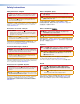
Safety Instructions Safety Instructions • English WARNING: This symbol, , when used on the product, is intended to alert the user of the presence of uninsulated dangerous voltage within the product’s enclosure that may present a risk of electric shock.
FCC Class A Notice This equipment has been tested and found to comply with the limits for a Class A digital device, pursuant to part 15 of the FCC rules. The Class A limits provide reasonable protection against harmful interference when the equipment is operated in a commercial environment. This equipment generates, uses, and can radiate radio frequency energy and, if not installed and used in accordance with the instruction manual, may cause harmful interference to radio communications.
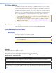
Contents Introduction............................................................ 1 Reference Information....................................... 10 About this Guide.................................................. 1 About the DTP DVI 330 Tx/Rx Transmitter and Receiver...................................................... 1 TP Cable Advantages...................................... 2 Control Communications................................. 2 Features.........................................................
DTP DVI 330 Tx/Rx Transmitter and Receiver • Introduction vi
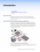
Introduction • About this Guide • About the DTP DVI 330 Transmitter and Receiver • Features About this Guide This guide describes the Extron DTP DVI 330 Long Distance Digital Visual Interface (DVI) Twisted Pair Extender, which consists of a DTP DVI 330 Tx transmitter and a DTP DVI 330 Rx receiver. This guide describes how to install, operate, and configure the transmitter and receiver.
The transmitter is shipped with a single external desktop 12 VDC power supply that accepts 100 to 240 VAC, 50-60 Hz input. A single power supply connected to either the transmitter or the receiver can power both units through the TP cable that carries DVI video. TP Cable Advantages Twisted pair cable is much smaller, lighter, more flexible, and less expensive than coaxial or DVI cable. These transmitter and receiver twisted pair (TP) products make cable runs simpler and less cumbersome.
Installation and Operation This section describes the installation and the operation of the DTP DVI 330 Tx/Rx Extender, including: • Mounting the Units • Connections • Operation Mounting the Units Mounting instructions can be found in Mounting the Transmitter or Receiver on page 10. Compatible optional hardware is listed on the Extron website (www.extron.com). ATTENTION: • Installation and service must be performed by authorized personnel only.
b Local Output connector — If desired, connect a DVI monitor for local monitoring of the input digital image. NOTES: • The local output is limited to a data rate of 4.95 Gbps (1.65 Gbps per color). • In a system where the local output is not used, ensure that you power up the end display first before the video source. Route the DDC to the remote end (see the DDC Route DIP switch [see item c on page 9]).
Receiver Connections POWER 12V 0.8 A MAX SIG RS-232 DTP IN Rear 11 Tx Rx 7 IR G L DVI-D AUDIO Tx Rx R DTP DVI 330 Rx Front 10 Figure 3. g OUTPUTS OVER DTP LINK 8 9 DTP DVI 330 Rx Connectors DTP Input RJ-45 connector — Connect one end of the TP cable from the transmitter output connector to this RJ-45 female connector. Ensure the opposite end of this cable is connected to the transmitter DTP Out connector (see item e on the previous page).
j RS-232 and IR connector — Connect a serial RS-232 signal, a modulated IR signal, or both to this 3.5 mm, 5-pole captive screw connector for bidirectional RS-232 and IR communication (see RS-232 and IR connector wiring on page 9 to wire the connector). k Power input connector — Plug the included external 12 VDC power supply into either this 2-pole connector or the power input connector on the transmitter (see item f on the previous page) (see Power supply wiring on page 8 to wire the connector).
Supported cables — The DTP DVI 330 is compatible with CAT 5e, 6, 6a, and 7 shielded twisted pair (F/UTP, SF/UTP, and S/FTP) and unshielded twisted pair (U/UTP) cable. Cable recommendations — Extron recommends using the following practices to achieve full transmission distances up to 330 feet (100 m) and reduce transmission errors.
Power supply wiring NOTES: • One power supply is included with the transmitter and normally can power both units. • If you have removed the ground jumpers (see Disconnecting the Ground on page 11) because of ground potential differences, one DTP DVI 330 unit cannot remotely power the other unit. Each unit requires a local power supply. Figure 6 shows how to wire the connector. Use the supplied tie-wrap to strap the power cord to the extended tail of the connector.
RS-232 and IR connector wiring Figure 7 shows how to wire the RS-232 connector. IR Device Rx Tx Gnd Tx Rx Tx Rx G IR RS-232 Tx/Rx Pins Tx Rx Gnd RS-232 Device Figure 7. RS-232 Connector Wiring NOTES: • The IR Tx and Rx line pair and the RS-232 Tx and Rx line pair must each cross once between this connector and the source or destination. • The length and preparation of exposed wires is important (see the second and third audio connector NOTES on page 5 for details).
Reference Information This section provides procedures for mounting the DTP DVI 330 Tx/Rx transmitter and receiver and disconnecting the ground between them. • Mounting the Transmitter or Receiver • Disconnecting the Ground Mounting the Transmitter or Receiver ATTENTION: • Installation and service must be performed by authorized personnel only.
UL Rack-Mounting Guidelines The following Underwriters Laboratories (UL) requirements pertain to the installation of the unit into a rack. • Elevated operating ambient temperature — If installed in a closed or multi-unit rack assembly, the operating ambient temperature of the rack environment may be greater than room ambient. Therefore, consider installing the equipment in an environment compatible with the maximum ambient temperature (TMA = +122 °F, +50 °C) specified by Extron.
3. Locate, lift off, and discard jumpers JMP2 and JMP3 from both units (see figure 10). JMP2 JMP3 JMP2 JMP3 Transmitter Figure 10. Receiver Jumper Locations 4. Reinstall the covers on both units, securing them in place with the screws removed in step 2. 5. Reinstall both units in their racks or other installation option (see Mounting the Transmitter and Receiver on page 10). 6. If you are using shielded cable, disconnect the cable shield from the connector at either end of the cable. 7.
Extron Warranty Extron Electronics warrants this product against defects in materials and workmanship for a period of three years from the date of purchase.