
User guide


DTP DVI 330 Tx/Rx Transmitter and Receiver • Installation and Operation 5
Receiver Connections
FrontRear
L R
OUTPUTS
DVI-D
AUDIO
DTP DVI 330 Rx
Rx GTx
RS-232 IR
RxTx
POWER
12V
0.8 A MAX
SIG LINK
DTP IN
OVER DTP
10 9
11 87
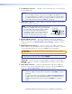
Figure 3. DTP DVI 330 Rx Connectors
g DTP Input RJ-45 connector — Connect one end of the TP cable from the transmitter
output connector to this RJ‑45 female connector. Ensure the opposite end of this cable
is connected to the transmitter DTP Out connector (see item e on the previous page).
ATTENTION: Do not connect this device to a telecommunications or computer
data network.
NOTE: See TP cable termination and recommendations on the next page to
properly wire the RJ‑45 connectors and for detailed NOTES.
Signal LED — Indicates the unit is receiving a valid signal on the DTP In connector.
Link LED — Indicates a valid link is established between the units on the DTP input
and output cable.
h DVI output connector — Connect a display with an DVI input port (or HDMI input
port, with an appropriate adapter) to display the transmitted direct digital image.
i Audio output connector — This 5‑pole, 3.5 mm captive screw connector outputs
the transmitted, unamplified, line level analog audio. Connect an audio device, such as
an audio amplifier or powered speakers.
See figure 4 to properly wire a captive screw output connector. Use the supplied
tie‑wrap to strap the audio cable to the extended tail of the connector.
Unbalanced Stereo Output Balanced Stereo Output
Do not tin the wires!
Tip
Ring
Tip
Ring
Sleeves
Tip
No Ground Here
No Ground Here
Tip
Sleeves
LR
LR
Figure 4. Captive Screw Connector Wiring for Stereo Audio Output
ATTENTION: For unbalanced audio, connect the sleeves to the ground contact.
Do not connect the sleeves to the negative (‑) contacts.
NOTES:
• If you have removed the ground jumpers (see Disconnecting the Ground on
page 11) because of ground potential differences, the DTP DVI 330 cannot
extend analog audio. No analog audio is output.
• The length of exposed wires is critical. The ideal length is 3/16 inch (5 mm).
• If the stripped section of wire is longer than 3/16 inch, the exposed wires
may touch, causing a short circuit.
• If the stripped section of wire is shorter than 3/16 inch, wires can be easily
pulled out even if tightly fastened by the captive screws.
• Do not tin the power supply leads before installing them in the connector.
Tinned wires are not as secure in the connector and could be pulled out.