
User guide


DTP DVI 330 Tx/Rx Transmitter and Receiver • Installation and Operation 6
j RS-232 and IR connector — Connect a serial RS‑232 signal, a modulated IR
signal, or both to this 3.5 mm, 5‑pole captive screw connector for bidirectional RS‑232
and IR communication (see RS-232 and IR connector wiring on page 9 to wire the
connector).
k Power input connector — Plug the included external 12 VDC power supply into
either this 2‑pole connector or the power input connector on the transmitter (see
item f on the previous page) (see Power supply wiring on page 8 to wire the
connector).
NOTES:
• One power supply is included with the transmitter and normally can power
both units.
• If you have removed the ground jumpers (see Disconnecting the Ground
on page 11) because of ground potential differences, one DTP DVI 330 unit
cannot remotely power the other unit. Each unit requires a local power
supply.
Connector and Cable Details
TP cable termination and recommendations
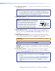
Figure 5 details the TIA/EIA T 568B wiring standard. Use this standard to terminate TP
cables with RJ‑45 connectors.
5
Pin
1
2
3
6
7
8
4
Wire color
White-green
Green
White-orange
White-blue
Orange
White-brown
Brown
Blue
TIA/EIA T
568 B
Side
12345678
Insert
Twisted
Pair Wires
Pins:
Figure 5. TP Cable Termination
NOTE: Do not use Extron UTP23SF‑4 Enhanced Skew‑Free AV UTP cable or STP201
cable to link the transmitter and receiver. The DTP DVI 330 Tx/Rx does not work
properly with these cables.