
Setup Guide Owner's manual


IMPORTANT:
Go to www.extron.com for the complete
user guide, installation instructions, and
specifications before connecting the
product to the power source.
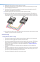
PC with DVI Output
DVI 104
Transmitter
DVI 104
Receiver
Hi-r
esolution
Flat Panel Displa
y
with DVI-D Inpu
t
4 Multi Mode
Fiber
Up to 500 meters (1640 feet)
DVI 104 Tx/Rx • Setup Guide
Description
The Extron DVI 104 Tx and DVI 104 Rx are fiber optic transmitter and receiver
units that extend DVI signals up to 500 meters (1,640 feet) using four multimode
fiber optic cables.
The transmitter plugs directly into the source device and the receiver plugs
directly into the display device.
The transmitter/receiver pair can handle DVI video signals with resolutions
up to 1920 x 1200 or 1080p at 60 Hz.
Optional four-fiber multimode cables are available in varying lengths.
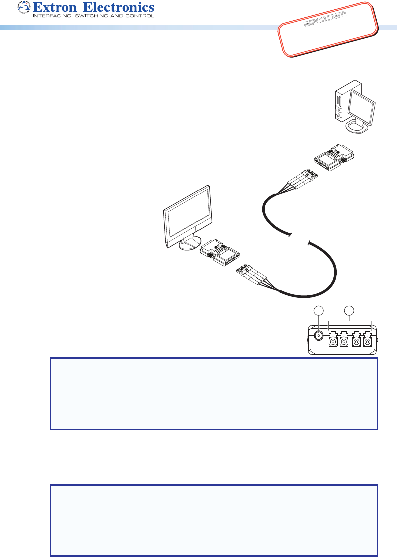
Front Panel Features
a
Power input — The transmitter and receiver both have plugs for a
1 2
3.5 mm jack to provide 5VDC to the unit.
The center pin of the jack carries +5 VDC; the outer shell of the jack
is the negative rail.
NOTES:
• If the source device is able to provide 5 VDC on pin 14 of its DVI output, the
transmitter can draw power from the source device. If the source is a laptop or a
PC using a PCI-E graphics card, it will not be able to provide enough power and
the transmitter must be powered with a separate external power supply.
• The receiver must be powered by an external power supply through the power
input plug.
b
LC Jacks — Four fiber optic cables connect the transmitter to the receiver. The cables
connect to the four female LC jacks in each of the units.
A label on the top panel identifies the unit as the transmitter or receiver and identifies the
fiber optic port numbers and the power input.
NOTES:
• For the transmitter, port 1 is closest to the power input and port4 is furthest
away. For the receiver, port 4 is closest to the power input and port 1 is furthest
away.
• Although the orientation is reversed, ports with the same number must be
connected by the same cable, so that port 1 on the receiver is connected to
port 1 on the transmitter, and so forth.
Insert the end of the fiber optic cable into the appropriate plug on the transmitter or
receiver. The locking catch should snap into the slot and hold the cable securely in place.