User’s Manual DVI 201 Tx/Rx HDMI 201 Tx/Rx Digital Video Transmitter and Receiver www.extron.com Extron Electronics, USA Extron Electronics, Europe Extron Electronics, Asia Extron Electronics, Japan 1230 South Lewis Street Anaheim, CA 92805 USA 714.491.1500 Fax 714.491.1517 Beeldschermweg 6C 3821 AH Amersfoort The Netherlands +31.33.453.4040 Fax +31.33.453.4050 135 Joo Seng Road, #04-01 PM Industrial Building Singapore 368363 +65.6383.4400 Fax +65.6383.
Table of Contents Chapter One • Introduction .................................................... 1-1 About this Manual .................................................................... 1-2 About the DVI 201 Tx/Rx and HDMI 201 Tx/Rx ............... 1-2 TP cable advantages .............................................................. 1-3 Serial communications........................................................... 1-3 Transmission distance ............................................................
Table of Contents, cont’d Appendix A • Reference Information..............................A-1 Specifications ..............................................................................A-2 DVI 201 and HDMI 201 Tx/Rx DVI 201 Tx/Rx Specifications .................................................A-2 HDMI 201 Tx/Rx Specifications .............................................A-5 Part Numbers ..............................................................................
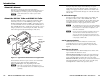
Introduction About this Manual This manual contains information about the Extron DVI 201 Tx/Rx and HDMI 201 Tx/Rx transmitter and receiver pairs, including how to install, operate, and configure them. N In this manual, the term "Tx/Rx" refers to either product. About the DVI 201 Tx/Rx and HDMI 201 Tx/Rx The Extron DVI 201 Tx/Rx is a Digital Visual Interface (DVI) transmitter/receiver set. The HDMI 201 Tx/Rx is a High Definition Multimedia Interface (HDMI™) transmitter/receiver set.
Introduction, cont’d Features Transmits single link DVI-D or HDMI signals over two CAT 5/5e/6/7 cables — Standard twisted pair cables provide an economical, easily installed cable solution. DVI 201 and HDMI 201 Tx/Rx Long distance transmission — CAT 5/5e/6 UTP cable — Accommodates 720p and 1080i HDTV or XGA video over 200' (60 m), and 1080p HDTV or UXGA (1600 x 1200) over 100' (30 m).
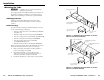
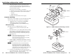
Installation Mounting the Tx/Rx C Installation and service must be performed by authorized personnel only. VersaTools Rack Shelf The 1" high, quarter-rack width transmitters and receivers can be placed on a tabletop, mounted on a rack shelf, mounted under a desk or tabletop, or mounted on a projector bracket. Tabletop placement Affix the four included rubber feet to the bottom of the transmitter or receiver unit and place it in any convenient location.
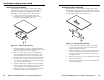
Installation and Operation, cont’d Under-furniture mounting The transmitter or receiver can be mounted under a table or other horizontal surface using an optional Extron MBU 125 under-desk mounting kit (part #70-077-01). Mount the transmitter or receiver under a desk or table as follows: 1. Through-furniture mounting The transmitter or receiver can be mounted through a desk or other furniture using an optional Extron MBD 129 through-desk mounting kit, part #70-077-02.
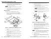
Installation and Operation, cont’d Slide the transmitter or receiver up and down in the mounting brackets until the face of the transmitter or receiver is at the desired height. Tighten the screws that secure the brackets in place. 5. If the screws are inaccessible to a screwdriver: Countoured Bracket Brace Side Mounting PLate U-Bolt Extron DVI 201 or HDMI 201 a. Mark the location of the brackets relative to the screws. Receiver b. Remove the transmitter or receiver from inside the furniture.
Installation and Operation, cont’d Place the U-bolt around the ceiling pole and insert the two legs of the U-bolt through the round holes on the contoured bracket base and then through the slotted holes on the bracket’s mounting plate. 5. N Assemble the U-bolt and the following parts in the following order (figure 2-8): 6. a. Pass the legs of the U-bolt through the slotted holes on the mount plate flange. The supplied U-bolt fits a typical (1.5" to 2.0" diameter) ceiling pole. b.
Installation and Operation, cont’d b Connections Transmitter connections The two transmitter models are in quarter-rack width enclosures. On the DVI 201 Tx (figure 2-9), the input and local monitor connectors are on the front panel and the rest of the connectors are on the rear panel. 1 2 DVI INPUT LOCAL OUTPUT DVI 200 Tx Series Front Panel c d e Rear Panel POWER 12V 0.4A MAX REMOTE LOCAL 1 2 5 6 On the HDMI 201 Tx (figure 2-10), all connectors are on the rear panel.
Installation and Operation, cont’d Receiver connections The two transmitter models are in quarter-rack width enclosures. On the DVI 201 Rx (figure 2-11), the RS-232 Pass-Through connector is on the front panel and the rest of the connectors are on the rear panel. 7 h i Receiver input connector — Connect one end of the two separate TP cables from the transmitter (item e on page 2-11) to these RJ-45 female connectors.
Installation and Operation, cont’d HDMI connector pin assignments Pin assignments and wiring Figure 2-14 define the pinout for the HDMI protocol. DVI connector pin assignments 1 Figure 2-13 define the pinout for the DVI protocol.
Installation and Operation, cont’d N TP cable termination N RJ-45 termination with CAT 5, CAT 5e, CAT 6, or CAT 7 cable must comply with the TIA/EIA T 568A wiring standard for all connections. Figure 2-15 details the recommended termination of TP cables with RJ-45 connectors in accordance with the TIA/EIA T 568A wiring standard.
Installation and Operation, cont’d 3. Peel the backing off the self-adhesive shielded aluminum tape and wrap it around the folded-over cable shielding, slightly overlapping the beginning of the tape (figure 2-17). Smooth Ridges A A SECTION A–A Aluminum Tape Wrap tape around folded foil shielding. Slightly overlap. Cut and save the excess tape for other connectors. Power Supply Output Cord Tie Wrap 0.3” (7 mm) MAX.
Installation and Operation, cont’d Transmitter control and indicator Operation DVI INPUT a LOCAL OUTPUT DVI 200 Tx SERIES b DVI 201 Tx Transmitter Front Panel 1 POWER 12V 0.4A MAX DVI 201 Tx DDC ROUTE REMOTE RS-232 PASS THRU SPARE 2 LOCAL 1 2 Power LED — This transmitter front panel LED lights to indicate that the unit is receiving power.
Installation and Operation, cont’d • High-bandwidth Digital Content Protection (HDCP) is an encryption method that protects copyrighted digital entertainment material that uses DVI video. HDCP is generated by video player hardware, enabled by the video content. The HDCP key is transmitted with the Display Data Channel (DDC). The DDC signal line was designed for the DDC’s low data rate; the HDCP key rate is much higher.
Reference Information Specifications DVI 201 Tx/Rx Specifications N This product consists of a transmitter (DVI 201 Tx) and a receiver (DVI 201 Rx) with twisted pair cables linking the transmitter and receiver. Interconnection between transmitter and receiver Connectors ..................................... (2) RJ-45 per unit for 2 CAT 5/5e/6 cables connecting the transmitter and receiver Bit rate ............................................. 5 gigabits/second total (1.
Reference Information, cont’d General HDMI 201 Tx/Rx Specifications External power supply ................. 100 VAC to 240 VAC, 50/60 Hz, external, autoswitchable; to 12 VDC, 1 A, regulated Power input requirements ........... 12 VDC, 0.4 A for both transmitter and receiver N Each transmitter or receiver can be powered either locally by an external power supply or remotely by receiver or transmitter on the other end of the CAT 5/5e/6 cables. Temperature/humidity ................
Reference Information, cont’d Digital audio ................................ HDMI audio, actively buffered (transmitted through RGB and YCrCb lines) RS-232 ............................................ RS-232 serial data (pass-through) (on a 3.5 mm captive screw connector, 3 pole) CEC ................................................ Consumer Electronics Control (CEC) wired infrared data using the HDMI standard (pass-through) EDID (DDC) .................................
Reference Information, cont’d Mounting accessories Part Numbers Accessories Transmitter/receiver pair part numbers N The Tx/Rx is comprised of the transmitter-receiver pair. The transmitter and receiver cannot be purchased separately.
Reference Information, cont’d A-10 DVI 201 and HDMI 201 Tx/Rx • Reference Information
Precautions Safety Instructions • English This symbol is intended to alert the user of important operating and maintenance (servicing) instructions in the literature provided with the equipment. This symbol is intended to alert the user of the presence of uninsulated dangerous voltage within the product’s enclosure that may present a risk of electric shock. Caution Read Instructions • Read and understand all safety and operating instructions before using the equipment.