
User`s manual

DVI 201 and HDMI 201 Tx/Rx • Installation and Operation
Installation and Operation, cont’d
2-8
DVI 201 and HDMI 201 Tx/Rx • Installation and Operation
2-9
5. Place the U-bolt around the ceiling pole and insert the
two legs of the U-bolt through the round holes on the
contoured bracket base and then through the slotted holes
on the bracket’s mounting plate.
N
The supplied U-bolt fi ts a typical (1.5" to 2.0" diameter)
ceiling pole.
6. Secure the bracket to the U-bolt with the included hex
nuts, washers, and lock washers. Tighten the hex nuts just
enough that they can be loosened by hand.
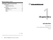
PMK 350 mounting
Mount the receiver to a PMK 350 bracket as follows:
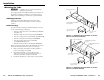
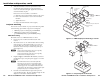
1. Remove the front and back plates from the PMK 350
(fi gure 2-7), using an Extron Tweeker or
a #2 Philips
screwdriver. Retain the screws to reattach the plates when
you are fi nished.
Extron
PMK 350
Multi-product Projector
Mounting Kit
Cover Sheet
Front Plate
Rear Plate
U-bolt
L-shaped
Bracket
Contoured
Base
Extron
Power Supply
Extron
Quarter-rack
Sized Product
Figure 2-7 — PMK 350 projector mounting a receiver
2. If necessary, remove the feet from the bottom of the
receiver.
3. Secure the receiver to one side of the mounting tray,
using two of the supplied 4-40 x 3/16" screws in opposite
(diagonal) corners.
4. If power supply is connected to the receiver, use the
two included tie wraps to strap the power supply to the
bracket.
5. Place the PMK 350 around the projector ceiling mounting
pole (fi gure 2-7).
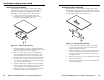
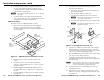
6. Assemble the U-bolt and the following parts in the
following order (fi gure 2-8):
a. Pass the legs of the U-bolt through the slotted holes on
the mount plate fl ange.
b. Place the legs around the projector pole.
c. Pass the legs through the holes in the contour base.
N
The pole fi ts snugly into the depression in the
center of the contoured base.
d. Pass the legs through the holes in the L-shaped bracket.
N
The supplied U-bolt fi ts a typical (1.5" to 2.0"
diameter) ceiling pole.
U-bolt
Slotted Hole
in PMK Tray
L-shaped
Bracket
L-shaped
Bracket Screws
Contoured
Base
Ceiling
Pole
Mount Plate
Flange
Figure 2-8 — Hanging the tray on the pole
7. Align the two slotted holes in the bottom of the L-shaped
bracket with the two slotted holes in the base of the tray,.
Secure the L-bracket to the base by inserting two provided
6-32 x 5/16" screws through the aligned slots.
8. Move the PMK 350 up to the desired location on the ceiling
pole, as close to the ceiling as desired.
9. Secure the L-shaped bracket to the U-bolt using the
included hex nuts, washers, and lock washers. Tighten the
hex nuts securely.
N
Be sure to tighten the hex nuts securely enough that the
PMK 350 does not slide down the ceiling pole. A socket
wrench is recommended to tighten the hex nuts.
10. Secure the front panel to the mounting tray with four of
the included #6 screws.
11. If desired, choose one of the provided four sizes of self-
adhesive cover sheets, and apply it to the underside of the
mounting tray.