
Setup Guide

2
DVI DA Plus Series • Setup Guide (Cont’d)
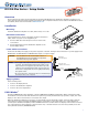
Part Number EDID Minder
Inactivation
DIP Switches
EDID Lock and
Pre-emphasis
DIP Switches
Rear Panel
DVI DA4 Plus
Disabling the EDID Minder
Some applications require that the EDID Minder feature is disabled for specific outputs or are ignored during the automatic
scanning process. To prevent EDID being read from specific outputs:
1. Remove and keep the screws holding the cover to the base (seven screws for the DVI DA4 Plus, ten screws for the
DVI DA6 Plus and DVI DA8 Plus). Save the screws and set aside the cover.
2. Check the part number of the printed circuit board (outlined in the figure above left). The boards must have a part
number of 20-1496-01LF and higher (DVI DA4 Plus) or 20-1497-01LF and higher (DVI DA6 Plus or DVI DA8 Plus).
NOTE: If the part number of the board is lower than these values, you cannot deactivate the EDID Minder on your
model. Replace the cover as described in step 5.
3. Locate the EDID Minder Inactivation DIP switches. The DVI DA4 Plus has a single bank of four switches (see the figure
above left). Each switch regulates the correspondingly numbered output (1-4).
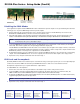
The DVI DA6 Plus and DVI DA8 Plus have two banks of four switches (see the figure above right). In bank 1, each switch
regulates the correspondingly numbered output (1-4). In bank 2, switches 1 and 2 correspond to outputs 5 and 6 for the
DVI DA6 Plus; switches 1-4 correspond to outputs 5-8 for the DVI DA8 Plus.
4. By default the switches are in the off/down position, allowing the EDID information to be read from the corresponding
output. To deactivate EDID Minder for one or more outputs, move the switch for that output to the on/up position.
5. Replace the cover, using the screws that were removed in step 1.
EDID Lock and Pre-emphasis
By default, EDID information stored at the input is lost when the unit goes through a power cycle or a new output display is
connected to the device. EDID Lock maintains specific EDID information so that it is not lost after these events.
Pre-emphasis compensates for poor signals delivered to output devices.
To enable EDID Lock or Pre-emphasis:
1. Remove the cover and locate the part numbers as described in steps 1 and 2 of the previous section.
2. Locate the EDID Lock and Pre-emphasis DIP switches (outlined in the figure above left). For all three models, the
EDID Lock DIP switch is labeled EDID Mode; the Pre-emphasis DIP switch is labeled Preemph.
3. By default, the EDID Mode and Pre-emphasis DIP switches are in the down (disabled) position. To enable either feature,
toggle the appropriate switch to the up position.
NOTE: Before enabling the EDID Lock feature, be sure the desired EDID is currently being used.
4. Replace the cover, using the screws that were removed in step 1.
Extron USA - West
Headquarters
+800.633.9876
Inside USA/Canada Only
+1.714.491.1500
+1.714.491.1517 FAX
Extron USA - East
+800.633.9876
Inside USA/Canada Only
+1.919.863.1794
+1.919.863.1797 FAX
Extron Europe
+800.3987.6673
Inside Europe Only
+31.33.453.4040
+31.33.453.4050 FAX
Extron Asia
+800.7339.8766
Inside Asia Only
+65.6383.4400
+65.6383.4664 FAX
Extron Japan
+81.3.3511.7655
+81.3.3511.7656 FAX
Extron China
+400.883.1568
Inside China Only
+86.21.3760.1568
+86.21.3760.1566 FAX
Extron Middle East
+971.4.2991800
+971.4.2991880 FAX
© 2011 Extron Electronics All rights reserved. www.extron.com
68-1536-50 Rev. C
02 11
EDID Disable DIP Switches for DVI DA6 (shown) and DVI DA8
Bank 1:
Outputs 1-4
Bank 2:
Outputs 5-6 (DVI DA6 Plus)
Outputs 5-8 (DVI DA8 Plus)