ES3610/11 VN-GLIMPSE RGB ADAPTER User Guide ELECTROSONIC
Contents ES3610/11 User Guide VN-GLIMPSE RGB ADAPTER USER GUIDE Part No. I447GB issue 6 (Nov 2008) Copyright © 2006 Electrosonic Ltd. All rights reserved. No part of this documentation may be reproduced or transmitted in any form or by any means, electronic or mechanical, including photocopying and recording, without the prior written permission of Electrosonic Ltd.
ES3610/11 User Guide Contents IMPORTANT SAFETY MARKINGS The following symbols are used throughout this User Guide to advise you of important instructions: This symbol warns the presence of a voltage of sufficient magnitude to cause a severe or fatal electric shock. Follow the appropriate instructions carefully to avoid the risk of injury. This symbol indicates an important instruction for the correct and safe installation, operation or maintenance of your RGB ADAPTER system.
Contents ES3610/11 User Guide Contents Contents .............................................................................. 4 SECTION 1: .......................................................................... 7 Introduction.............................................................................................7 What is the VN-GLIMPSE RGB ADAPTER? ................................................................ 8 Single or Multiple Users ..........................................................
ES3610/11 User Guide Contents Connection Diagram (Analog Source) ....................................................................................... 25 Connecting the RGB ADAPTER to a Network ........................................................................... 26 Network Requirements ........................................................................................................... 26 Setting the Correct IP Address ........................................................................
Contents ES3610/11 User Guide Using the ‘Ping’ Utility to Test Communications ........................................................................ 54 Response Messages .............................................................................................................. 54 APPENDIX B:...................................................................... 55 Understanding VN-GLIMPSE Performance ..........................................55 Understanding VN-GLIMPSE Performance....................
ES3610/11 User Guide Section 1: Introduction SECTION 1: Introduction I447GB issue 6 Page 7
Section 1: Introduction ES3610/11 User Guide What is the VN-GLIMPSE RGB ADAPTER? The VN-GLIMPSE RGB ADAPTER is used to distribute an RGB monitor signal from a source computer (or similar graphical device) across an IP network to a viewing station. At its simplest the viewing station can be another computer, running the VN-GLIMPSE VIEWER software application.
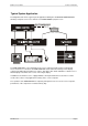
ES3610/11 User Guide Section 1: Introduction Typical System Application The diagram below shows a typical system application utilizing the VN-GLIMPSE RGB ADAPTER allowing a computer source to be viewed on a VISIONETWORK (VN) Processor: The RGB ADAPTER is connected between the source computer and its monitor, keyboard and mouse. From these connections the RGB ADAPTER collects data about changes in the display content along with keyboard and mouse actions.
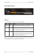
Section 1: Introduction ES3610/11 User Guide Front Panel Features Indicators The following indicators are visible on the front of the RGB ADAPTER: Name Color Function POWER Green Lit when the unit is receiving power from the 12V supply input. NETWORK Orange Indicates the status of the Ethernet connection: Flashing Intermittently – data is being transmitted across the network. Unlit – no network connection detected.
ES3610/11 User Guide Section 1: Introduction Rear Panel Features Full details of connector types, pin-outs and specifications can be found in Section 5:Technical Data. Briefly, these are as follows: Power Supply Input The RGB ADAPTER requires a 12V power supply via this connector. A suitable mains operated power supply unit (PSU) is provided. Network Connector This connects the RGB ADAPTOR to the viewing station, usually via an Ethernet network. Captured image data is output from here.
Section 1: Introduction ES3610/11 User Guide Source Compatibility The RGB ADAPTER is compatible with both digital (DVI) and analog graphics sources up to UXGA resolution (1600 x 1200 @ 60Hz, 24-bit color). See page 48 for a list of standard supported sources. The RGB ADAPTER incorporates advanced image acquisition circuitry which can auto-detect a wide range of source types without the need for any additional setup.
ES3610/11 User Guide Section 1: Introduction Control Capability Local keyboard and mouse control of the source computer is fully maintained while connected to the RGB ADAPTER. In addition, keyboard and mouse functions can be remotely controlled from the viewing station. Little or no internal configuration is required in order to use the RGB ADAPTER.
Section 1: Introduction ES3610/11 User Guide Accessories Supplied Accessories In addition to this User Guide, the RGB ADAPTER is supplied with the following accessories. If any of these items is missing or damaged, please contact your Electrosonic dealer immediately: Item Qty Re-order Code 12V Power Supply Unit (PSU) Note: ES3610-P has a square-style connector; ES3611-P has a round-style connector.
ES3610/11 User Guide Section 2: Installation SECTION 2: Installation I447GB issue 6 Page 15
Section 2: Installation ES3610/11 User Guide Choosing a Suitable Location The VN-GLIMPSE RGB ADAPTER is designed to be used either as a free-standing unit or (by using the optional kit available) to be mounted in a 19 inch equipment rack. CAUTION Whichever installation method you choose there are certain environmental requirements, detailed on page 17, which must be observed in order to ensure safe and reliable operation.
ES3610/11 User Guide Section 2: Installation Environmental Requirements CAUTION The criteria on this page must be observed for all installations of the RGB ADAPTER, whether free-standing or rack-mounted. Orientation The RGB ADAPTER must be operated in the horizontal position only. When used free-standing it must be placed on a stable, flat and level surface. Ensure that the surface finish will not be affected by the heat produced by the RGB ADAPTER when in use.
Section 2: Installation ES3610/11 User Guide Rack-mount Requirements CAUTION For rack-mounted installations, the following criteria must be observed (in addition to the Environmental Requirements listed on page 17) Mounting & Support ALWAYS use the special rack-mount kit (available separately) to secure the RGB ADAPTER. Full details on using the kit are included with the kit.
ES3610/11 User Guide Section 2: Installation Mains Power Connection (via PSU) The RGB ADAPTER must be powered from a 12 Volt DC regulated supply. A suitable mains-operated power supply unit (PSU) is provided. The mains connection details that follow relate to the PSU. NEVER CONNECT THE RGB ADAPTER DIRECTLY TO THE MAINS. ALWAYS use the PSU provided. If a backup/replacement PSU is required, always use an Electrosonic approved PSU.
Section 2: Installation ES3610/11 User Guide Mains Power Cord (for PSU) The mains PSU is equipped with a 3-pin (male) type mains connector which requires a power cord fitted with a corresponding 3-pin IEC320 (female) connector. Two power cords are supplied with the PSU, each having a different termination; you must use the lead appropriate for your country: In... Use the... Re-order Code USA and Canada cord fitted with the 3-pin American-style ‘Edison’ plug.
ES3610/11 User Guide Section 2: Installation Fitting a Mains Plug If you are fitting a plug to the unterminated power cord (or replacing an existing plug), you must fit a plug that: • • • • is rated for use with mains voltage is equipped with a grounding pin/connection complies with any applicable National or Local electrical regulations. is fitted with a correctly rated fuse (applicable to UK-style plugs only – see page 22.
Section 2: Installation ES3610/11 User Guide External Supply Protection The mains power cord supplied with this product is rated at 10A maximum and must be protected from overload by an external fuse or circuit breaker. Fused Plugs (UK-style) If the power cord is fitted with a UK-style BS1363 3-pin plug (i.e. with provision for an internal fuse), then it must be fitted with a BS1362 ASTA approved 1 inch cartridge fuse. This fuse must be rated at a maximum of 10A/250V.
ES3610/11 User Guide Section 2: Installation Connecting to a Computer The RGB ADAPTER is compatible with both digital (DVI) and analog graphics signals. The unit is provided with the necessary additional cables that you will require. For a Digital Source… Use the following cables (replacement kit no. ES3610-CD) and refer to the connection diagram on page 24. • • Mouse/Keyboard Cable (PS/2 to PS/2) (2 off), Digital Monitor Cable (DVI-D to DVI-D).
Section 2: Installation ES3610/11 User Guide Connection Diagram (Digital Source) Page 24 I447GB issue 6
ES3610/11 User Guide Section 2: Installation Connection Diagram (Analog Source) I447GB issue 6 Page 25
Section 2: Installation ES3610/11 User Guide Connecting the RGB ADAPTER to a Network Source content captured by the RGB ADAPTER is transmitted to the viewing device using TCP/IP. The unit therefore requires a connection to an Ethernet network. CAUTION: Do not proceed with connecting or configuring the RGB ADAPTER for an existing network until you are certain you know what you are doing – incorrect connection or configuration may cause disruption to other network users.
ES3610/11 User Guide Section 3: VN-GLIMPSE Setup Utility SECTION 3: VN-GLIMPSE Setup Utility I447GB issue 6 Page 27
Section 3: VN-GLIMPSE Setup Utility ES3610/11 User Guide Introduction In many applications no special setup or configuration of the RGB ADAPTER will be required other than to set its IP Address and Subnet Mask. Any RGB ADAPTER configuration that is required is achieved by means of the VN-GLIMPSE Setup Utility provided on the Software Disc. The Setup Utility must be installed and run on a suitable PC or laptop computer (the ‘configuration computer’).
ES3610/11 User Guide Section 3: VN-GLIMPSE Setup Utility Installing the Setup Utility Minimum Computer Specification The VN-GLIMPSE Setup Utility must be installed on a computer that meets or exceeds the following minimum specification: Minimum Recommended Operating System Windows NT4 (SP6) Windows 2000, XP Processor Any processor with MMX instruction set Pentium 3 or higher Memory (RAM) 64MB 128MB Hard Disk Free Space 1MB >1MB Graphics 1024x768, 65K colors (16-bit) 1024x768, 16.
Section 3: VN-GLIMPSE Setup Utility ES3610/11 User Guide Using the VN-GLIMPSE Setup Utility To start the Setup Utlity… From the Start menu, choose Programs | Electrosonic | GlimpseConfigure. The Choose Glimpse dialog will appear, listing all VN-GLIMPSE RGB ADAPTERS found on the network: Click on the address of the unit you want to connect to, and then click the OK button.
ES3610/11 User Guide Section 3: VN-GLIMPSE Setup Utility To change Network Settings (including IP Address)… Click the Network Settings button. The Change Network Settings dialog will appear: Change the settings as required. HINT: Here you can set a new IP address, subnet mask or select DHCP (automatic assignment of an address by the host network). In addition, you can assign a name to the RGB ADAPTER; this will require you to specify the address of a DNS and WINS server as well as the name.
Section 3: VN-GLIMPSE Setup Utility ES3610/11 User Guide Click OK to continue. The following dialog will now appear: To reboot the RGB ADAPTER and implement the new settings now, click Yes. Otherwise, click No — the settings will be implemented the next time that the RGB ADAPTER is rebooted. To change Encoder Parameters (Stream Settings)… Click the Stream Settings button. The Set Stream Settings dialog will appear: To change the maximum refresh rate, adjust the Frames/Sec value.
ES3610/11 User Guide Section 4: VN-GLIMPSE VIEWER SECTION 4: VN-GLIMPSE VIEWER I447GB issue 6 Page 33
Section 4: VN-GLIMPSE VIEWER ES3610/11 User Guide Introduction The VN-GLIMPSE VIEWER is a small software application that is used to display VN-GLIMPSE sources on a conventional computer or laptop. VN-GLIMPSE sources are captured using either: • • VN-GLIMPSE SERVER (software-based capture), or VN-GLIMPSE RGB ADAPTER (hardware-based capture) Any number of VN-GLIMPSE sources can exist on a given network. VN-GLIMPSE VIEWER can connect to only one source at a time.
ES3610/11 User Guide Section 4: VN-GLIMPSE VIEWER Using the VN-GLIMPSE VIEWER To start the VN-GLIMPSE VIEWER… From the Start menu, choose Programs | Electrosonic | VN-GlimpseViewer. VN-GLIMPSE VIEWER will now begin detecting VN-GLIMPSE sources available on the network. This process may take several seconds to complete, especially if there are a large number of sources. The VIEWER interface will then appear: On the left-hand side is the Source Window which displays the currently ‘connected’ source.
Section 4: VN-GLIMPSE VIEWER ES3610/11 User Guide To refresh the Source List… The Channel List is not automatically updated to show the current status of all sources. For example, if a new source is added once VN-GLIMPSE VIEWER has been started, it will not automatically appear in the source list. To ensure that the list of VN-GLIMPSE sources is up-to-date you can manually refresh it (i.e.
ES3610/11 User Guide Section 4: VN-GLIMPSE VIEWER Source Connection and Disconnection To connect to a Source using the Channel List… Double-click the required source name or IP Address in the Channel List. Alternatively, highlight the required source (single-click) then click the Connect button on the toolbar.
Section 4: VN-GLIMPSE VIEWER ES3610/11 User Guide Viewing Options The VN-GLIMPSE VIEWER provides a number of options for setting the viewing environment. You can choose to: • • • • View the source at its original resolution (unity) or scaled to fit the available window size. View the source full screen (i.e. without the menu bar, toolbar, channel list, etc.) Hide/show the VIEWER toolbar, channel list and/or status bar. Hide/show the current source refresh rate and data bandwidth on the status bar.
ES3610/11 User Guide Section 4: VN-GLIMPSE VIEWER Remote Mouse and Keyboard Control This feature allows the mouse and keyboard (of the computer running VN-GLIMPSE VIEWER) to emulate mouse and keyboard operation on the source computer. Remote mouse and keyboard control can be used with software agents and also with hardware agents that are operating in TCP unicast mode. Hardware agents operating in UDP multicast mode cannot be remotely controlled since they can have more than one viewing client connected.
Section 4: VN-GLIMPSE VIEWER ES3610/11 User Guide Using Mouse and Keyboard Control To use remote mouse and keyboard control you first need to ‘connect’ to the source and open a viewer window (as described on page 38). To start a mouse and keyboard control session… Click anywhere in the source area of the viewer window. A red border will appear around the source area, showing that a control session is now active. You can now use the mouse and keyboard to control the source computer.
ES3610/11 User Guide Section 4: VN-GLIMPSE VIEWER Learning Dialogs When performing certain operations, VN-GLIMPSE VIEWER displays a ‘learning dialog’ giving helpful tips and information. As you get more familiar with using VIEWER you may prefer to turn off these dialogs. From the Tools menu, choose Options to open the following dialog: Uncheck the appropriate boxes to disable the learning dialogs, then click OK.
Section 4: VN-GLIMPSE VIEWER ES3610/11 User Guide Command line switch options The VN-GLIMPSE VIEWER may be launched with a number of command line switches that affect its startup behavior.
ES3610/11 User Guide Section 5: Technical Data SECTION 5: Technical Data I447GB issue 6 Page 43
Section 5: Technical Data ES3610/11 User Guide Mechanical Data Overall Dimensions: Average Weight: 200mm (7.9 inches) 155mm (6.125 inches) [including rear sockets] 44mm (1.75 inches) [excluding rubber feet] 47mm (1.85 inches) [including rubber feet] 0.67 kg (1.5 lbs) Width: Depth: Height: Operating Conditions Ambient Temperature: Ambient Humidity: Location: 5°C to 35°C (41°F to 95°F). 85% maximum (non-condensing). Free-standing or 19” Rack-mounting (using approved kit).
ES3610/11 User Guide Section 5: Technical Data Control Inputs/Outputs Keyboard/Mouse Connectors Function: Connector Type: Pin-out Details: Keyboard and mouse pass-through connections for source computer. 6-pin mini-DIN (female) Pin 1 2 3 4 5 6 Function Data No connection Ground +5V supply* Clock No connection * 5V on pin 4 limited to 200mA by thermal fuse. Mating Connector: Recommended Cable: Max. Cable Length: I447GB issue 6 6-pin mini-DIN (male). Supplied PS/2 cable. 2.95 metres (9.5 feet).
Section 5: Technical Data ES3610/11 User Guide Monitor Connectors Function: Connector Type: Pin-out Details: Monitor pass-through connections for source computer. DVI-I (female).
ES3610/11 User Guide Section 5: Technical Data Supported Source Formats Source Resolution Digital Analog H & V Sync Composite Sync Sync on Green 640x480@60Hz 640x480@72Hz 640x480@75Hz 640x480@85Hz 600x800@56Hz 600x800@60Hz 600x800@72Hz 600x800@75Hz 600x800@85Hz 1024x768@60Hz 1024x768@70Hz 1024x768@72Hz 1024x768@75Hz 1024x768@85Hz 1152x864@75Hz 1280x1024@60Hz 1280x1024
Section 5: Technical Data ES3610/11 User Guide Network Connector Function: Connector Type: Pin-out Details: Connection to a local area network and/or control PC. Shielded RJ-45 Socket. Pin 1 2 3 4 Mating Connector: Recommended Cable: Max. Cable Length: Comms Standard: Ethernet (MAC) Address: IP Address: Page 48 Function TD+ (+ data transmit) TD- (- data transmit) RD+ (+ data receive) NC Pin 5 6 7 8 Function NC RD- (- data receive) NC NC Shielded RJ-45 Plug. Shielded twisted pair (STP).
ES3610/11 User Guide Section 5: Technical Data Serial (RS-232) Connectors Function: Connector Type: Pin-out Details: COM1 – used for low level setup or system recovery. COM2 – reserved for future expansion. 9-pin D-type (male) Pin 1 2 3 4 5 Mating Connector: Recommended Cable: Max.
Appendix A: Guide to IP Addressing ES3610/11 User Guide APPENDIX A: Guide to IP Addressing Page 50 I447GB issue 6
ES3610/11 User Guide Appendix A: Guide to IP Addressing What is an IP Address? A full explanation of IP addressing is beyond the scope of this user guide. However the following details will provide you with enough information to get started. An IP Address is a 32-bit binary number that is used to identify each device on an Ethernet network. This number is usually represented by four decimal numbers (each in the range 0 to 255) separated by dots, e.g. 198.123.34.240.
Appendix A: Guide to IP Addressing ES3610/11 User Guide Choosing IP Addresses If your RGB ADAPTER(s) and control PC are directly connected, or connected via their own independent network, then follow the guidelines below for choosing your IP Address(es). However, if you intend connecting your RGB ADAPTER (s) and control PC to an existing network, you will need to advise the network administrator and ask them to allocate suitable addresses to you.
ES3610/11 User Guide Appendix A: Guide to IP Addressing Using the ‘Ping’ Utility to Test Communications You can test for communications between a Windows computer and another device on the same network by using the Windows Ping utility. From the Windows Desktop of the computer, click on the Start button, and select Run from the pop-up menu. The Run dialog box will appear. In the Open box, type in the following command: ping xxx.xxx.xxx.xxx –t where xxx.xxx.xxx.xxx is the IP Address of the device (e.g.
ES3610/11 User Guide Appendix B: Understanding VN-GLIMPSE Performance APPENDIX B: Understanding VN-GLIMPSE Performance Page 54 I447GB issue 6
Appendix B: Understanding VN-GLIMPSE Performance ES3610/11 User Guide Understanding VN-GLIMPSE Performance In an ideal VN-GLIMSPE system, the source seen at the viewing station should be virtually indistinguishable from the original source. However, in certain circumstances, you may notice some reduction in performance. The following details are intended to explain the problems you may encounter and how to minimize or avoid them.
ES3610/11 User Guide Appendix B: Understanding VN-GLIMPSE Performance What can affect these criteria? Data Stream ‘Bottlenecks’ The VN-GLIMPSE RGB ADAPTER only streams data relating to ‘changes’ in the source display. Therefore, a source containing a lot of movement (e.g. an MPEG movie) will create more data than a source with little or no movement (e.g. a spreadsheet file).
Appendix B: Understanding VN-GLIMPSE Performance ES3610/11 User Guide Adjusting the Encoder Parameters Using the VN-GLIMPSE Setup Utility (see page 32) you can set the following parameters: • Bandwidth Limit – If you are using a large number of RGB ADPATERS or you have a slow/busy network, you can reduce this value which sets the maximum possible flow of data being streamed onto the network.
ES3610/11 User Guide Appendix B: Understanding VN-GLIMPSE Performance This page is intentionally left blank.
rh=J=içåÇçå e~ïäÉó=jáääI=e~ïäÉó=oç~ÇI=a~êíÑçêÇI=hÉåíK=a^O=Tpv qÉäW=HQQ=NPOO=OOO=ONN==c~ñW=HQQ=NPOO=OUO=OUO bJã~áäW=áåÑçêã~íáçå]ÉäÉÅíêçëçåáÅJìâKÅçã rp^=J=jáååÉ~éçäáë NMPOM=_êÉå=oç~Ç=b~ëíI=jáååÉíçåâ~I=jk=RRPQP qÉäW=HN=VRO=VPN=TRMM==c~ñW=HN=VRO=VPU=VPNN bJã~áäW=áåÑçêã~íáçå]ÉäÉÅíêçëçåáÅKÅçã rp^=J=içë=^åÖÉäÉë PPOM=kçêíÜ=p~å=cÉêå~åÇç=_äîÇI=_ìêÄ~åâI=`^=VNRMQ qÉäW=HN=UNU=PPP=PSMM==c~ñW=HN=UNU=RSS=QVOP bJã~áäW=áåÑçêã~íáçå]ÉäÉÅíêçëçåáÅKÅçã rp^=J=kÉï=vçêâ NN=e=mêáåÅÉëë=oç~ÇI=i~ïêÉåÅÉîáääÉI=kg=MUSQU qÉäW=HN=SMV=ONV=VQV