User’s Manual DVI 101 and HDMI 101 Cable Equalizers 68-1447-01 Rev.
Precautions Safety Instructions • English This symbol is intended to alert the user of important operating and maintenance (servicing) instructions in the literature provided with the equipment. This symbol is intended to alert the user of the presence of uninsulated dangerous voltage within the product’s enclosure that may present a risk of electric shock. Caution Read Instructions • Read and understand all safety and operating instructions before using the equipment.
安全须知 • 中文 警告 这个符号提示用户该设备用户手册中 有重要的操作和维护说明。 电源 • 该 设 备 只 能 使 用 产 品 上 标 明 的 电 源 。 设 备 必须使用有地线的供电系统供电。 第三条线 (地线)是安全设施,不能不用或跳过。 这个符号警告用户该设备机壳内有暴 拔掉电源 • 为安全地从设备拔掉电源,请拔掉所有设备后 或桌面电源的电源线,或任何接到市电系统的电源线。 露的危险电压,有触电危险。 电源线保护 • 妥善布线, 避免被踩踏,或重物挤压。 注意 阅读说明书 • 用 户 使 用 该 设 备 前 必 须 阅 读 并 理 解所有安全和使用说明。 保存说明书 • 用户应保存安全说明书以备将来使 用。 遵守警告 • 用户应遵守产品和用户指南上的所有安 全和操作说明。 维护 • 所有维修必须由认证的维修人员进行。 设备内部没 有用户可以更换的零件。为避免出现触电危险不要自己 试图打开设备盖子维修该设备。 通风孔 • 有些设备机壳上有通风槽或孔,它们是用来防止 机内敏感元件过热。 不要用任何东西挡住通风孔。 锂电池 • 不正确的更换电池会有爆炸的危险。 必须使用与 厂家推荐的相同
T
Table of Contents Chapter One • Introduction ..................................................... 1-1 About this Manual ..................................................................... 1-2 About the DVI 101 and HDMI 101 Cable Equalizers ....... 1-2 Features ......................................................................................... 1-3 Application Diagrams . .............................................................. 1-3 Chapter Two • Installation and Operation . ..................
Table of Contents, cont’d ii DVI 101 and HDMI 101 • Table of Contents
DVI 101 and HDMI 101 Equalizers 1 Chapter One Introduction About this Manual About the DVI 101 and HDMI 101 Cable Equalizers Features Application Diagrams
Introduction About this Manual This manual contains information about the Extron DVI 101 and HDMI 101 Cable Equalizers and describes procedures for connecting and operating them. In this manual, the term “equalizer” is used to refer to either the DVI 101 or the HDMI 101 Cable Equalizer. "DVI/HDMI" refers to either product or to both products.
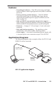
Features • Power/Signal indicator — The LED on the front panel lights green to indicate source signal presence and yellow to indicate power on. • Source-powering at short distances — The DVI/HDMI can receive power from an attached input source device, eliminating the need for power supply installation (see the table on page 2-8). • DDC and HDCP copy protection transmission support — DDC channels are actively buffered, allowing pass-through of EDID and HDCP information between source and display.
Introduction, cont’d Long HDMI Cable 200’ (61 m) Max. MI HD T PU UT R WE PO X V 12 MA 0.
DVI 101 and HDMI 101 Equalizers 2 Chapter Two Installation and Operation Mounting the DVI 101 and HDMI 101 Front and Back Panel Features and Connections Powering Via the Input Source Connecting for Long Cable Runs
Installation and Operation Mounting the DVI 101 and HDMI 101 The DVI 101 and HDMI 101 can be mounted on a rack shelf, under furniture, or placed on a table top. See "Optional Accessories", in appendix A, "Specifications, Parts, and Accessories", for information on the mounting products available for the DVI/HDMI 101. Tabletop use Four self-adhesive rubber feet are included with the DVI/HDMI. For tabletop use, attach one foot at each corner on the bottom surface of the unit.
Rack mounting procedure For optional rack mounting, mount the DVI/HDMI on one of the rack shelves listed above. On the standard 9.5" or 6" deep rack shelf, the equalizer mounts in one of eight possible locations to the rear of the rack. Use 2 mounting holes on opposite corners. 1/4 Rack Width Front False Faceplate Both front false faceplates use 2 screws. 1/2 Rack Width Front False Faceplate (2) 4-40 x 3/16" Screws 1U Universal Rack Shelf Mounting the DVI 101 or HDMI 101 on a standard 9.
Installation and Operation, cont’d Furniture mounting To mount the DVI 101 or the HDMI 101 under a desk top, podium, or other furniture, use the optional MBU 125 Underdesk Mounting Kit (part #70-077-01), as follows: 1. If rubber feet were previously attached to the bottom of the unit, remove them. 2. Remove the screws from one side of the DVI/HDMI. Retain the screws for possible later reassembly. 3.
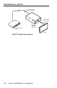
Front and Back Panel Features and Connections 2 DVI-D INPUT 1 POWER 12V 0.2A MAX DVI 101 DVI-D OUTPUT 6 4 DVI 101 front and rear panels 3 HDMI INPUT 1 POWER 12V 0.
Installation and Operation, cont’d a Power/signal status LED — This dual-color LED lights yellow when the DVI/HDMI is receiving power. When a DVI or HDMI input signal is present, this LED lights green. If the LED does not light when you are attempting to power the unit from the source device, use an external power supply instead. N b DVI input connector (DVI 101 only) — Plug the cable from the input source device into this single link format female DVI-I connector.
c HDMI input connector (HDMI 101 only) — Plug the cable from the input source device into this female HDMI type A connector. The table and diagrams below show the HDMI pin configuration.
Installation and Operation, cont’d Recommended maximum cable lengths Powered from source Powered from external supply 640x480 480p 150' (46 m) 275' (84 m) 1024x768 1280x1024 720p 1080i 150' (46 m) 250' (76 m) 125' (38 m) 200' (61 m) Video resolution 1600x1200 1920x1200 1080p d DVI output connector (DVI 101 only) — Plug the cable from a DVI output device into this single link format DVI-I connector, following the pin configuration shown in the table on page 2-6. Output signals are digital only.
C When you are connecting the power supply, voltage polarity is extremely important. Applying power with incorrect voltage polarity could damage the power supply and the equalizer. Identify the negative lead by the ridges on the side of the cord (see the illustration on page 2-8). C Do not tin the stripped power supply leads before installing the captive screw connector. Tinned wires are not as secure in the captive screw connectors and could be pulled out.
Installation and Operation, cont’d 2-10 DVI 101 and HDMI 101 • Installation and Operation
DVI 101 and HDMI 101 Equalizers A Appendix A Specifications, Parts, and Accessories Specifications – DVI 101 Specifications – HDMI 101 Included Parts Optional Accessories Cables and Adapters
Specifications, Parts, and Accessories Specifications – DVI 101 N Appropriate HDMI-to-DVI cables or adapters are required for HDMI signal input/output. Video Maximum data rate ���������������������� Pixel clock frequency �������������������� Resolution range ��������������������������� Formats ������������������������������������������� Standards ���������������������������������������� 4.95 Gbps (1.65 Gbps per color) 165 MHz (maximum) Up to 1920x1200 or 1080p @ 60 Hz RGB and YCbCr digital video DVI 1.
Power input requirements ����������� 12 VDC, 0.2 A from an external power supply or 5 VDC, 0.05 A from a DVI source or an HDMI source Temperature/humidity ���������������� Storage: -40 to +158 °F (-40 to +70 °C) / 10% to 90%, noncondensing Operating: +32 to +122 °F (0 to +50 °C) / 10% to 90%, noncondensing Cooling ������������������������������������������� Convection, no vents Mounting Rack mount ������������������������ Yes, with optional 1U, 9.
Specifications, Parts, and Accessories, cont’d Specifications – HDMI 101 N Appropriate DVI-to-HDMI cables or adapters are required for DVI signal input/output. Video Maximum data rate ���������������������� Pixel clock frequency �������������������� Resolution range ��������������������������� Formats ������������������������������������������� Standards ���������������������������������������� 4.95 Gbps (1.65 Gbps per color) 1.
Power input requirements ����������� 12 VDC, 0.2 A from an external power supply or 5 VDC, 0.05 A from an HDMI or DVI source Temperature/humidity ���������������� Storage: -40 to +158 °F (-40 to +70 °C) / 10% to 90%, noncondensing Operating: +32 to +122 °F (0 to +50 °C) / 10% to 90%, noncondensing Cooling ������������������������������������������� Convection, no vents Rack mount ������������������������������������ Yes, with optional 1U, 9.
Specifications, Parts, and Accessories, cont’d Included Parts DVI 101 These items are included in each order for the DVI 101: Included parts Replacement part number DVI 101 Equalizer 60-873-01 12 VDC, 1 A external power supply kit 70-055-01 3.
Optional Accessories The following items are optional and can be purchased separately for the DVI 101 and/or the HDMI 101. Accessories Part number MBU 125 Under-desk Mount Kit 70-077-01 RSU 129 1U, 9.5" deep, universal rack shelf kit 60-190-01 RSB 129 1U, 9.5" deep, basic rack shelf 60-604-01 RSU 126 1U, 6" deep, universal rack shelf kit 60-190-10 RSB 126 1U, 6" deep, basic rack shelf 60-604-10 RSF 123 1U, 3.5" deep, VersaTools rack shelf kit 60-190-20 RSB 123 1U, 3.
Specifications, Parts, and Accessories, cont’d This page was intentionally left blank.
Extron’s Warranty Extron Electronics warrants this product against defects in materials and workmanship for a period of three years from the date of purchase.
Extron USA - West Headquarters +800.633.9876 Inside USA / Canada Only +1.714.491.1500 +1.714.491.1517 FAX Extron USA - East Extron Europe Extron Asia Extron Japan Extron China Extron Middle East +800.633.9876 +800.3987.6673 +800.7339.8766 +81.3.3511.7655 +81.3.3511.7656 FAX +400.883.1568 +971.4.2991800 +971.4.2991880 FAX +1.919.863.1794 +1.919.863.1797 FAX +31.33.453.4040 +31.33.453.4050 FAX +65.6383.4400 +65.6383.