User Guide Audio Products XTRA™ Series Half-Rack Audio Power Amplifiers 68-2354-01 Rev.
Safety Instructions Safety Instructions • English WARNING: This symbol, , when used on the product, is intended to alert the user of the presence of uninsulated dangerous voltage within the product’s enclosure that may present a risk of electric shock. ATTENTION: This symbol, , when used on the product, is intended to alert the user of important operating and maintenance (servicing) instructions in the literature provided with the equipment.
FCC Class B Notice This equipment has been tested and found to comply with the limits for a Class B digital device, pursuant to part 15 of the FCC rules. These limits provide reasonable protection against harmful interference in a residential installation. This equipment generates, uses, and can radiate radio frequency energy and, if not installed and used in accordance with the instructions, may cause harmful interference to radio communications. There is no guarantee that interference will not occur.
Contents Introduction................................................... 1 Operation........................................................ 9 About this Manual............................................ 1 Terms Used in this Manual............................ 1 Features........................................................... 1 Front Panel Features and Operation................. 9 Rear Panel Features and Operation................ 11 Remote Volume Control..............................
Introduction About this Manual This manual contains information about the Extron XTRA Series of power amplifiers. • XPA 1002 two-channel stereo audio power amplifier • XPA 1002 Plus two-channel stereo audio power amplifier • XPA 2001-70V mono audio power amplifier • XPA 2001-100V mono audio power amplifier Terms Used in this Manual The terms “amplifier” and “power amplifier” are used interchangeably in this manual to refer to all of the XPA models. “XPA 1002” refers to the 1002 and the 1002 Plus.
Extron patented CDRS — Class D ripple suppression — A patented, exclusive technology from Extron that eliminates the high frequency switching ripple and EMI emissions found in typical Class D amplifiers. CDRS enables Extron power amplifiers to be situated near wireless AV devices without RF interference. Convection cooled — The XTRA Series of amplifiers are convection cooled without the need for fans, ensuring quiet, reliable operation.
Installation This section discusses how to install the XTRA Series of audio power amplifiers. Topics that are covered, include: • Application Examples • Mounting the XTRA Series Amplifier WARNING: Failure to follow these instructions may result in serious injury. Installation and service must be performed by authorized personnel only (see UL Guidelines for Rack Mounting on page 4). Application Examples The following illustrations are application examples for the XPA 1002 series and the XPA 2001 series.
Extron SI 26CT Two-way Ceiling Speakers Extron XPA 2001-70V Power Amplifier T TPU 50m 10V G V OU ING SS 2 WIR CLA )R HPF STANDBY 70 OTE REM A UTS INP GlobalViewer MED L (SUM ON V ATI C G ENU ATT V AV Resource Management and Remote Control Application -70 01 A 20 XP 12 14 18 26 ∞ 0Hz 0.
2. Reduced air flow — Installation of the equipment in a rack should be such that the amount of air flow required for safe operation of the equipment is not compromised. 3. Mechanical loading — Mounting of the equipment in the rack should be such that a hazardous condition is not achieved due to uneven mechanical loading. 4.
Rack Mounting Ventilation Recommendations Excessive heat can decrease the optimal lifetime of the power amplifier. An over temp indicator LED on the front panel of the amplifier lights red whenever the recommended operating temperature has been exceeded (see Front Panel Features and Operation on page 9). To reduce the chances for an over temp condition, the XPAs should be arranged in a rack environment so that adequate airflow is available both above and below the XPA whenever possible.
The optional Flexible Conduit Adapter Kit consists of: • One EMT adapter plate • One 6-foot long electrical conduit • Three 7.5 feet, 18-gauge spade connector power wires • One UL-rated zip tie wrap • Three auxiliary crimp style spade connectors designed for 14- to 16-gauge wires NOTE: If needed, Extron recommends using a UL-rated crimp tool to terminate the spade connectors. One recommended choice is the Molex crimp tool.
3. Remove the 2 screws holding the hot (Line) and neutral wires from the terminal block on the PCB (see figure 6). Blue Wire Brown Wire 100- 240V 1.3A 50-6 0H z N L Remove nut Remove screws (both sides) to release IEC connector plate. Figure 6. Removing the IEC Connector 4. Remove the ground wire nut from the grounding stud on the bottom of the enclosure, as shown above. 5.
Operation This section discusses how to operate the XTRA Series of audio power amplifiers.
c Limiter/Protect indicator LEDs — These LEDs (representing their respective output channels) light red under three circumstances: 1 2 LIMITER/PROTECT • When the output wiring is shorted together. • When audio clipping occurs, the LED of the corresponding channel blinks once per clip occurrence. • When the amplifier overheats, both LEDs are lit. The LEDs are not lit after the amplifier recovers from the overheated condition. NOTE: These LEDs are duplicated on the rear panel.
Rear Panel Features and Operation 2 0.5A, 50-60Hz XPA 1002 INPUTS ATTENUATION 2 1 1 LIMITER/PROTECT SIGNAL XPA 1002 XPA 1002 Plus Rear Panel 1 1 2 2 4 3 8Ω / 4Ω OUTPUTS REMOTE 10V 50mA 12 10 8 12 10 8 6 14 6 14 18 4 4 2 2 26 ∞ 0 ∞ 0 G 5a STANDBY 100-240V 6 1 2 7a 2 0.
d Attenuation — Use a small screwdriver to adjust the audio input level for the corresponding channel. The analog potentiometers control the level from = (full attenuation) to 0 dB (no attenuation).
R Balanced Mono Input Unbalanced Mono Input Do not tin the wires! INPUTS 1 NOTE: The input connector receptacle may be labeled one of two ways. The wiring and function are the same, whichever way your product is labeled. â Tip Ring Sleeve R Balanced Stereo Input Unbalanced Stereo Input L L Tip Sleeve R R Tip Ring Sleeves Tip Ring L L Tip Sleeve Tip Sleeve INPUTS 2 2 1 or Balanced or unbalanced stereo or mono audio input connector (XPA 2001) — Wire the 3.
10V 10V 50mA G V STANDBY REMOTE or 1 50 mA VOL/MUTE 2 3 C G 4 5 STANDBY 1 V MAX MUTE 2K OHMS 2 C 10K OHMS MUTE SWITCH MIN VOLUME 3 G Pin 5 (standby) connected to ground (pin 4) places the amplifier in standby mode. Standby mode turns off all output, although the amplifier is still receiving power. Use the included 2-pin, 3.5 mm captive screw connector to remotely ground pin 5. The power indicator LED lights amber when the amplifier is in standby mode.
8Ω/4Ω OUTPUTS 1 OUTPUT 1 2 2 or CLASS 2 WIRING XPA 1002 XPA 1002 Plus ATTENTION: Do not tie channel outputs 1 and 2 to each other or to ground. Doing so will short the outputs, damage the amplifier, or both. NOTE: The power output of the XPA 1002 series can be effectively doubled by bridging the output. A mono source is wired to both the left and right input while the output is wired for bridged operation. Bridging allows power to be output at 200 watts into 8 ohms.
ç Mono audio output connector — Wire the included 2-pole, 5 mm screw lock captive screw connector for mono audio (see the steps below). Output is designed to power 70 V (XPA 2001-70V) or 100 V (XPA 2001-100V) line distribution systems and is rated at 200 watts. NOTES: • You must use Class 2 wiring for this output to comply with UL requirements. • The mono audio output connector may be labeled one of two ways (see the images below).
h High pass filter (HPF) toggle switch (XPA 2001 series) — Use a small screwdriver to toggle this recessed two-position switch. Setting the switch to 80 Hz (default) prevents the saturation of 70 V and 100 V speaker input transformers by low frequency signals. Saturation can result in severe distortion of the speaker output signal. HPF HPF 80 Hz 80 Hz or OFF OFF NOTES: • The filter may be safely turned off if high pass filtering is applied to the source input signal upstream of the amplifier.
Controlling Multiple Amplifiers with One Volume Controller Several XPA 1002 and XPA 2001 series units can be daisy-chained so that one volume controller can simultaneously regulate the volume of all the amplifiers. NOTES: • As additional amplifiers are added to the daisy chain, the sensitivity of the volume potentiometer will change. The maximum volume level (fully clockwise) will not be affected.
Bridged Mono Output The power output of the XPA 1002 and XPA 1002 Plus can be effectively doubled by bridging the output. Bridging power to be output in mono at 200 at 8toohms. ATTENTION: Failureallows to follow these instructions may result in watts damage the unit. Electrostatic discharge (ESD) can damage IC chips even though you cannot feel it. You must NOTES: • The bridging instructions that follow apply only to the XPA 1002 series. • The minimum load impedance when bridging is 8 ohms.
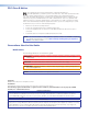
Troubleshooting The front and rear panels have LED warning indicators, as described in the following diagnostic information. Amplifier Fails to Exit Standby Mode Promptly The input channel (channels 1 and 2) Signal LED lights green per indicated input channel when an input signal is detected. Power LED Signal LED Problem Description Color State Problem Solution Amber Not lit No input detected, verify the input signal. If input is present, raise input level until signal LED lights.
Amplifier Enters Standby Mode Too Early The input channel (channels 1 and 2) Signal LED lights green per indicated input channel when an input signal is detected. Power LED Signal LED Color State Problem Description Problem Solution Green or Amber Enters standby mode early. Lit intermittently The output signal level of the source may be too low to cross the signal detection threshold of the amplifier (see amplifier specifications for details).
Extron Warranty Extron Electronics warrants this product against defects in materials and workmanship for a period of three years from the date of purchase.