User’s Manual HSA 822M Motorized Hideaway Surface Access Enclosure ® Extron USA - West Headquarters +800.633.9876 Inside USA / Canada Only +1.714.491.1500 +1.714.491.1517 FAX Extron USA - East Extron Europe Extron Asia Extron Japan Extron China Extron Middle East +800.633.9876 +800.3987.6673 +800.7339.8766 +81.3.3511.7655 +81.3.3511.7656 FAX +400.883.1568 +971.4.2991800 +971.4.2991880 FAX +1.919.863.1794 +1.919.863.1797 FAX +31.33.453.4040 +31.33.453.4050 FAX +65.6383.4400 +65.6383.
Precautions Safety Instructions • English This symbol is intended to alert the user of important operating and maintenance (servicing) instructions in the literature provided with the equipment. This symbol is intended to alert the user of the presence of uninsulated dangerous voltage within the product’s enclosure that may present a risk of electric shock. Caution Read Instructions • Read and understand all safety and operating instructions before using the equipment.
ᅝܼ乏ⶹ s Ё᭛ 䖭Ͼヺোᦤ⼎⫼᠋䆹䆒⫼᠋ݠЁ ᳝䞡㽕ⱘ᪡㓈ᡸ䇈ᯢDŽ 䖭Ͼヺো䄺ਞ⫼᠋䆹䆒ᴎݙ᳝ᲈ 䴆ⱘॅ䰽⬉य़ˈ᳝㾺⬉ॅ䰽DŽ ⊼ᛣ 䯙䇏䇈ᯢк s 䑩ㅸỀ䑩嬦嫿⡈⼆枼敆嬼䍇夤ㆁ 㙊⫊₩⏍Ề䑩嬵㕏ɿ ֱᄬ䇈ᯢк s 䑩ㅸⷕ⪙⫊₩嬵㕏ᶧḦ⡈⭇㚦Ề 䑩ɿ 䙉ᅜ䄺ਞ s 䑩ㅸⷕ徶⫉ᷨ␂⏍䑩ㅸ㉈⊘ᵋ䗅ㆁ㙊⫊ ₩⏍㐎ẝ嬵㕏ɿ 䙓ܡ䗑ࡴ s ᵎ壂Ề䑩嬦ᷨ␂⋃⒇㯢㙊㋩劑䗅₸ㅗ 弾⇡嫿⡈澤Ḧ忀₎⊲斪ɿ 䄺ਞ ⬉⑤ s 嬦嫿⡈⌫倾Ề䑩ᷨ␂ᵋ㝈㕏䗅䑶㷑ɿ 嫿⡈⼆枼Ề䑩 㙊♱一䗅Ờ䑶䰼丠Ờ䑶ɿ 䩭ᵊ㚢一澠♱一澡㕰⫊₩嫿 㓾澤ᵎ倾ᵎ䑩ㅗ崴弈ɿ ᢨᥝ⬉⑤ s ᵻ⫊₩♱ḏ嫿⡈㈕㋊䑶㷑澤嬸㈕㋊ㆁ㙊嫿⡈⍏ ㅗ㞍暣䑶㷑䗅䑶㷑一澤ㅗḼẖ㋦ⅱⵃ䑶䰼丠䗅䑶㷑一ɿ ⬉⑤㒓ֱᡸ s ⣦Ⓟⵄ一澤 忀₎埬嵪嵐澤ㅗ愎䆪㉥⋌ɿ 㓈ᡸ s ㆁ㙊丵Ἧ⼆枼䑲嫥嬂䗅丵Ἧ᷻⎙弜垍ɿ 嫿⡈怩㯢 㙊䑩ㅸ⌰Ḧ㘵㊣䗅昷ḷɿᵻ忀₎℻䋱大䑶⊲斪ᵎ壂儫ⴲ 嬖☿㆔⹁嫿⡈䘗⪑丵Ἧ嬦嫿⡈ɿ 䗮亢ᄨ s 㙊ᷜ嫿⡈㙻⠴ᵋ㙊彛栏㤾ㅗ⪕澤⫄ḭ㕰䑩㚦敳㪣 㙻㒐だ₄ḷ弈䀮ɿ ᵎ壂䑩Ḽẖᵝ壀㉢Ẑ彛栏⪕ɿ 䫖⬉∴ s ᵎ㪤䞯䗅㘵㊣䑶㮡ṛ㙊䅇㿹䗅⊲斪ɿ ⼆枼Ề䑩
Table of Contents Chapter 1 • Introduction .......................................................... 1-1 About the HSA 822M Hideaway® Enclosures .......... 1-2 Features ...................................................................................... 1-4 Chapter 2 • Installation ............................................................. 2-1 Installation Overview .......................................................... 2-2 Preparing the Routing Template ...................................
Table of Contents, cont’d Appendix A • Reference Information ............................ A-1 Specifications ......................................................................... A-2 Part Numbers .......................................................................... A-4 HSA 822M .............................................................................. Included parts ....................................................................... Template, replacement parts, and accessories .............
Introduction About the HSA 822M Hideaway® Enclosures The Extron HSA 822M is a furniture-mounted, motorized, architectural solution for inconspicuous computer video interface connector access and control. The HSA 822M (figure 1-1) provides space for four double space (double-height) or eight single space Extron Architectural Adapter Plates (AAPs), two standard grounded AC power receptacles, and four RJ-45 (Category [CAT] 6) connectors.
Introduction, cont’d The HSA 822M is available in a variety of surface finishes, including black anodized aluminum, brushed aluminum, brushed brass, and polished aluminum.
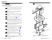
Installation CAUTION Installation and service must be performed by authorized personnel only. 11 Connect power cords and turn on the devices that connect to the surface access enclosure. Installation Overview See figure 2-1 and the following steps to install the HSA 822M: 1 2 If desired, install the optional flexible conduit kit to replace the removable AC power cord. Refer to the Flexible Conduit Kit manual. 3 If you have an unprepared mounting template, prepare the template.
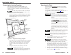
Installation, cont’d Preparing the Routing Template Preparing the Table Extron offers a metal template, part #70-191-01, for the HSA 822M and HSA 822. Extron recommends using this template as a guide to cut the hole in the table where the HSA will be installed. The metal routing template is reusable. Do not discard this template when the installation is complete. Save it for future HSA 822M installations. 1.
Installation, cont’d 7. Carefully lower the HSA enclosure into the hole to test the fit. If necessary, remove the enclosure and use a file or rasp to enlarge or smooth the edges of the opening. Cabling and Installing the AAPs The space behind the AAP panel is limited. The online Connectivity Configurator, available at www.extron.com, offers guidance as to the fit of AAPs into this space.
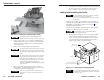
Installation, cont’d Ensure that the edges of the AAP/RJ-45 panels do not scratch the finished surface of the top panel flange when removing the panels. 2. Cable the rear of the AAPs before fastening the AAPs to the AAP/RJ-45 panel. Route the cables through the hole in the underside of the surface mount enclosure and connect them to the rear of the AAPs. If applicable, refer to the cabling information in the documentation for the AAP. 3.
Installation, cont’d 3. From the underside of the table, bolt the clamshell to the enclosure with two bolts of optimum length (included) (see figure 2-1 on page 2-3). 4. Experiment with AAP cable positioning between the enclosure and the clamshell to ensure that the cables do not rub against the edges of the AAP cable access hole and to ensure that the cable pull does not restrict the movement of the top panel. Figure 2-7 shows the cables routed to the side, which proved effective in tests at Extron.
Installation, cont’d Cabling the RJ-45 connectors Plug one end of a terminated CAT 5 or CAT 6 twisted pair (TP) cable into each of these RJ-45 female connectors. Connect the other end to an appropriate telecommunications or data network device or to an Extron TP product. Cabling the control and status captive screw connector Plug one end of the control cable(s) into this 10-pole captive screw connector. Connect the other end of the cable(s) to a control and/or monitoring system.
Installation, cont’d If connected to the power status pin, the LED is lit when power is applied to the HSA. Figure 2-13 shows a typical locally-constructed contact closure control and LED indication device. 1 2 3 4 5 7 6 Pwr status Stop Down Up +12 V Down status HSA 822M Up status Enable Figure 2-11 shows the function of the HSA’s status pins (6 [up], 7 [down], and 9 [power]). When a status condition is met, the switch closes, shorting the status pin to ground, pulling it low.
Installation, cont’d Bezels The HSA 822M ships with RJ-45/RJ-11 connector bezel plug-ins in a variety of colors and a black, blank bezel. Bezel To change to a different color RJ-45 connector bezel or if an RJ-45 connector is not needed or desired, replace the connector bezel plug-in on the AAP/RJ-45 panel with a bezel of a different color or a blank plug-in. See “Replacing the Bezels” in chapter 3.
Maintenance and Modifications CAUTION Installation and service must be performed by authorized personnel only. This chapter provides the following procedures: Maintenance procedures marked with an asterisk (*) require removing the HSA 822M from the table.
Maintenance and Modifications, cont’d 3. Disconnect any cables from the rear of the AAP(s) that are being replaced. 4. If an AAP cable is no longer required in your system, on the underside of the clamshell, cut the tie wraps that route the AAP cables out of the way. 5. If an AAP cable is no longer required in your system, on the underside of the table, remove the two bolts (shown at right) that secure the clamshell to the surface mount enclosure and remove the clamshell. 6.
Maintenance and Modifications, cont’d 4. Snap a replacement bezel in place. If necessary, replace the connector icon by prying the old icon off of the connector plug-in with a Tweeker (figure 3-4) and snapping a new icon in place. Removing and Replacing the Enclosure Many maintenance procedures require removing the HSA 822M from the table. Remove and replace the surface mount enclosure as follows: 1. Activate the motor to raise the platform and then disconnect the AC power.
Maintenance and Modifications, cont’d 9. On the underside of the table, remove the two bolts that secure the clamshell to the surface mount enclosure and remove the clamshell (figure 3-5). 10. From the underside of the enclosure, reach into the cable access holes (figure 3-1 on page 3-2, item 3 ), and cut the tie wraps ( 5 ) that route the AAP cables and network (CAT 6) cables inside the enclosure. Carefully pull the cables through and out the bottom of the HSA. 11. Lift the enclosure out of the table.
Maintenance and Modifications, cont’d You do not need to remove the screws in the center of two of the sides. They do not secure the shroud in any way; rather, they provide structural support to the enclosure. 13. Perform the desired maintenance procedure. 14. Secure the two shroud halves to the enclosure frame with the eight screws per shroud half (four per side) removed in step 2.
Maintenance and Modifications, cont’d 5. Loosen the upper limit lock nut. 6. Rotate the upper limit set screw: Upper Limit Switch Switch (Hidden) Actuator Clockwise (tighten) to lower the upper limit of platform motion. Counterclockwise (loosen) to raise the upper limit of platform motion. 2. Lower Limit Set Screw Upper Limit Lock Nut Lower Limit Lock Nut Upper Limit Set Screw Lower Limit Switch Adjustments do not take effect immediately.
Maintenance and Modifications, cont’d Setting the Manual Release Switch 4. This switch’s position is properly set in the factory. The manual release switch sets the amount of pressure needed to activate the press-to-activate feature. If the switch is set too low, you may have to push too hard on the platform. If the switch is set too high, the drive mechanism may activate sporadically. It is unlikely that the position of the manual release switch will ever need adjustment.
Maintenance and Modifications, cont’d Safety Switch — Location Only The safety switch (figure 3-10) stops the downward motion of platform when it encounters an obstruction to its smooth operation. If an obstruction is present that blocks the platform’s travel, the stepper motor’s carriage lifts and activates the safety switch. The HSA’s motor logic automatically reverses the platform’s motion and raises the platform to the upper position.
Maintenance and Modifications, cont’d HSA 822M A Appendix A Reference Information Specifications Part Numbers Top Plate Dimensions 3-18 HSA 822M • Maintenance and Modifications
Reference Information Specifications Control/remote Contact closure .............. (1) 3.5 mm female captive screw connector, 10 pole Contact closure/level pin configuration Pin 1 = up, pin 2 = down, pin 3 = stop, pin 5 = enable push operation, pin 6 = status up, pin 7 = status down, pin 9 = status power, pins 4, 8, and 10 = ground A General The Universal AC outlet is fully compatible with Europlug, British, Indian, Danish, and Italian plug types.
Reference Information, cont’d Interface accessories Part Numbers Accessory HSA 822M HSA 822M Part number HSA 822M US Enclosure (black anodized) 60-719-0A HSA 822M International Enclosure (black anodized) 60-719-nn The USA version of the HSA 822M is also available in a brushed aluminum finish. Visit the Extron Web site, www.extron.com for more part numbers. For the international versions, the nn in the part number identifies the AC power connector and finish (black anodized or brushed aluminum).
Reference Information, cont’d HSA 822M cut-out template Top Plate Dimensions The preferred and recommended method for cutting the table is to use the metal routing template, part #70-191-01 (figure A-2 and chapter 2, “Installation”). Cut-Out Template for Extron's HSA 822M User Access (Connectors and AAP Openings) 8.470" (21.51 cm) 6.220" (15.80 cm) 7.900 + 0.0325" (20.07 + 0.083 cm) 8.750" (22.23 cm) USER ACCESS USER ACCESS EXTRON ELECTRONICS 6.500" (16.51 cm) SURFACE CUT-OUT AREA = 7.900 + 0.
Reference Information, cont’d HSA 822M B Appendix B Packaging for Shipment A-8 HSA 822M • Reference Information
Packaging for Shipment CAUTION Installation and service must be performed by authorized personnel only. The HSA 822M’s ultra-fine machined surfaces and moving parts make them vulnerable to damage caused by mishandling during shipment if they are improperly packaged. If, for any reason, you need to return an HSA to Extron, first contact Extron to obtain a return kit.
Packaging for Shipment, Cont’d 3. Bolt the clamshell to the enclosure with two bolts and flat washers included in the return kit (figure B-3). 5. Install the rubber strips that protect the flanged edges of the top of the surface enclosure (figure B-4). Figure B-4 — Installing protective strips 6. Insert the HSA 822M and the clamshell into one of the foam shells (figure B-5). Either open end of the clamshell and the open top panel fits into the recesses in the foam.
Packaging for Shipment, Cont’d 7. Insert the opposite end of the HSA 822M and the clamshell into the remaining foam shell (figure B-6). Firmly push the foam shells together as far as they will go to completely suspend the HSA and clamshell. The sides of the clamshell protrude through slots in the foam. 8. Lower the foam-protected HSA into the shipping carton (figure B-7).